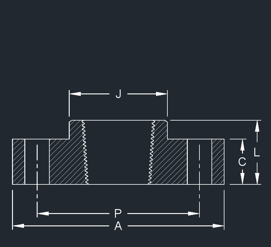
Flange - Threaded, ANSI Class 125, C115, DI (in) | ||||||||
|---|---|---|---|---|---|---|---|---|
| Pipe
Size (NPS) | Outside
Diameter of Flange A | Thickness
of Flange
| Diameter
of Hub at Base
| Length
of Hub
| Number
of Bolt Holes | Diameter
of Bolt Holes | Bolt
Circle Diameter
| Approx.
Weight |
| 3 | 7 1/2 | 3/4 | - | - | 4 | 3/4 | 6 | - |
| 4 | 9 | 15/16 | - | - | 8 | 3/4 | 7 1/2 | - |
| 6 | 11 | 1 | - | - | 8 | 7/8 | 9 1/2 | - |
| 8 | 13 1/2 | 1 1/8 | - | - | 8 | 7/8 | 11 3/4 | - |
| 10 | 16 | 1 3/16 | - | - | 12 | 1 | 14 1/4 | - |
| 12 | 19 | 1 1/4 | - | - | 12 | 1 | 17 | - |
| 14 | 21 | 1 3/8 | - | - | 12 | 1 1/8 | 18 3/4 | - |
| 16 | 23 1/2 | 1 7/16 | - | - | 16 | 1 1/8 | 21 1/4 | - |
| 18 | 25 | 1 9/16 | - | - | 16 | 1 1/4 | 22 3/4 | - |
| 20 | 27 1/2 | 1 11/16 | - | - | 20 | 1 1/4 | 25 | - |
| 24 | 32 | 1 7/8 | - | - | 20 | 1 3/8 | 29 1/2 | - |
| 30 | 38 3/4 | 2 1/8 | - | - | 28 | 1 3/8 | 36 | - |
| 36 | 46 | 2 3/8 | - | - | 32 | 1 5/8 | 42 3/4 | - |
| 42 | 53 | 2 5/8 | - | - | 36 | 1 5/8 | 49 1/2 | - |
| 48 | 59 1/2 | 2 3/4 | - | - | 44 | 1 5/8 | 56 | - |
| 54 | 66 1/4 | 3 | - | - | 44 | 2 | 62 3/4 | - |
| 60 | 73 | 3 1/8 | - | - | 52 | 2 | 69 1/4 | - |
| 64 | 80 | 3 3/8 | - | - | 52 | 2 | 76 | - |
- ANSI/AWWA C115/A21.15 - American National Standard for Flanged Cast-Iron and Ductile-Iron Pipe with Threaded Flanges.
- Class 125 flanges are plain faced without projection and are furnished smooth or with shallow serrations.
- The bolt circle and bolt holes of these flanges match those of ANSI/AWWA C115/A21.15 and Class 125 flanges shown in ANSI/ASME B16.1 and can be joined with A21.15 and Class 125 B16.1 flanges.
- The flanges do not match the Class 250 flanges shown in ANSI/ASME B16.1 and cannot be joined with Class 250 ANSI/ASME B16.1 flanged fittings and valves.
- Pipe face-to-face dimensions conform to a tolerance of ±.12" for sizes 3"-64"
- 3" to 12" = ±.12
- 14" to 24" = ±.19
- 30" to 64" = ±.25
![]()