- See Article - Beam Design Formulas
Simple Beam - Load Increasing Uniformly to Center formulas |
||
|
R=Vmax=W2 Vx[x<(L/2)]=W2⋅L2⋅(L2−4⋅x2) Mmax(atcenter)=W⋅L6 Mx[x<(L/2)]=W⋅x⋅(12−2⋅x23⋅L2) Δmax(atcenter)=W⋅L360⋅λ⋅I Δx[x<(L/2)]=W⋅x480⋅λ⋅I⋅L2⋅(5⋅L2−4⋅x2)2 |
||
| Symbol | English | Metric |
| R = reaction load at bearing point | lbf | N |
| V = maximum shear force | lbf | N |
| M = maximum bending moment | lbf−in | N−mm |
| Δ = deflection or deformation | in | mm |
| W = total load or wL/2 | lbf | N |
| w = highest load per unit length of UIL | lbf/in | N/m |
| L = span length of the bending member | in | mm |
| x = horizontal distance from reaction to point on beam | in | mm |
| λ (Greek symbol lambda) = modulus of elasticity | lbf/in2 | Pa |
| I = second moment of area (moment of inertia) | in4 | mm4 |
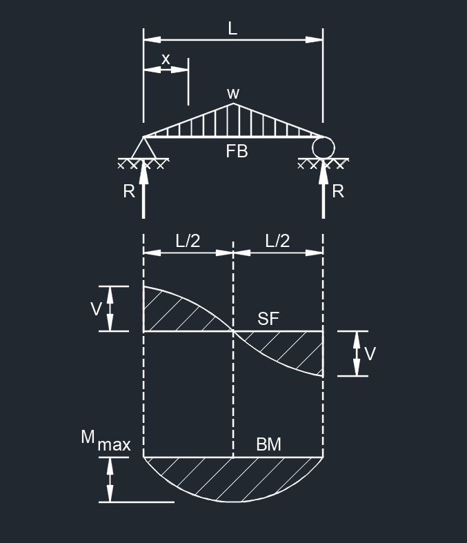
Diagram Symbols
Bending moment diagram (BMD) - Used to determine the bending moment at a given point of a structural element. The diagram can help determine the type, size, and material of a member in a structure so that a given set of loads can be supported without structural failure.
Free body diagram (FBD) - Used to visualize the applied forces, moments, and resulting reactions on a structure in a given condition.
Shear force diagram (SFD) - Used to determine the shear force at a given point of a structural element. The diagram can help determine the type, size, and material of a member in a structure so that a given set of loads can be supported without structural failure.
Uniformly distributed load (UDL) - A load that is distributed evenly across the entire length of the support area.
![]()