Structural beam design is the process of determining the appropriate size and shape of beams that will be used in construction to support and distribute loads within a building or structure. Beams are horizontal or inclined structural members that carry vertical loads. The design of structural beams involves several important considerations to ensure the safety, stability, and efficiency of a structure.
See Articles |
See Articles |
Key Points about Design of Structural Beams
Diagram Symbols
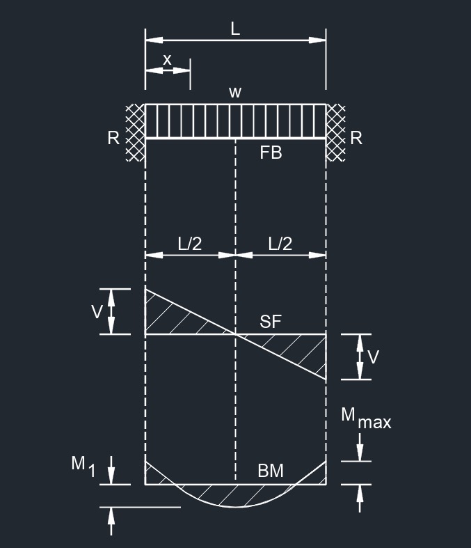
Simple Supported Beam
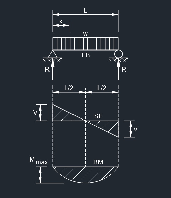 Uniformly Distributed Load
 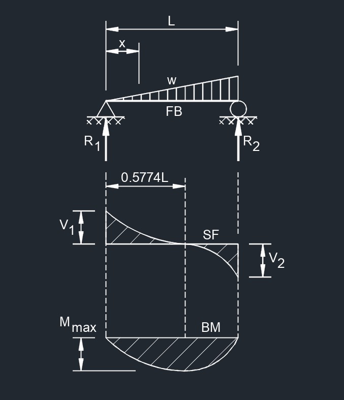 Load Increasing Uniformly to One End
 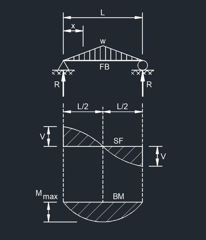 Load Increasing Uniformly to Center
 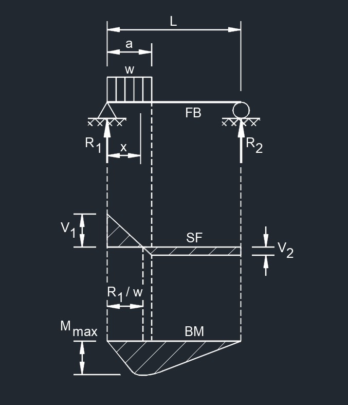 Uniform Load Partially Distributed at One End
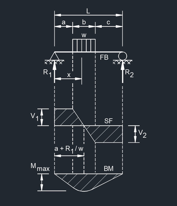 Uniform Load Partially Distributed at Any Point
 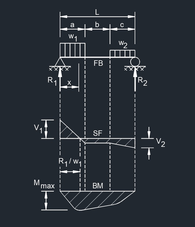 Uniform Load Partially Distributed at Each End
 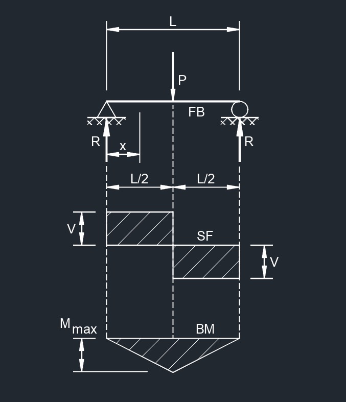 Concentrated Load at Center
 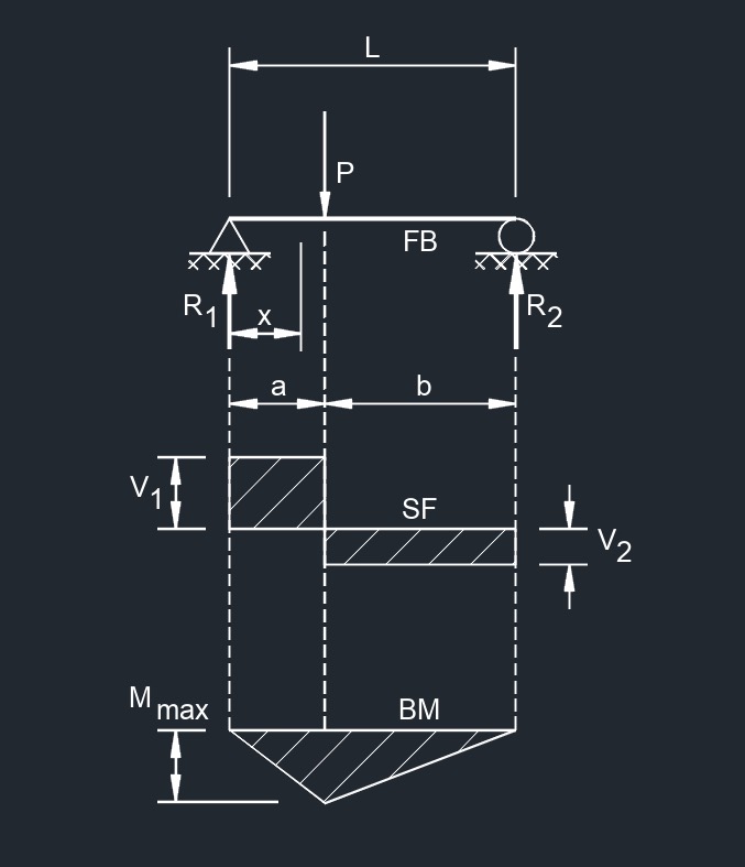 Concentrated Load at Any Point
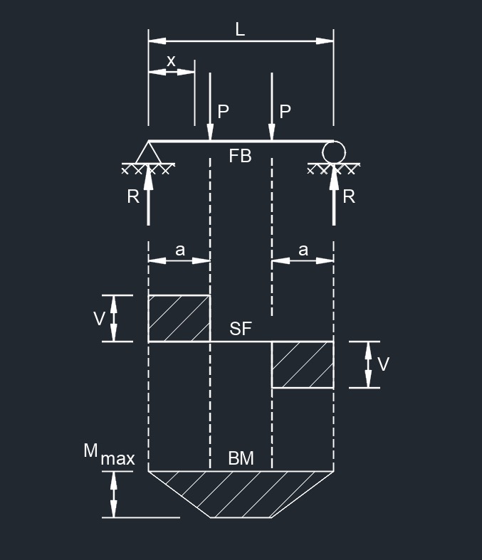 Two Point Loads Equally Spaced
 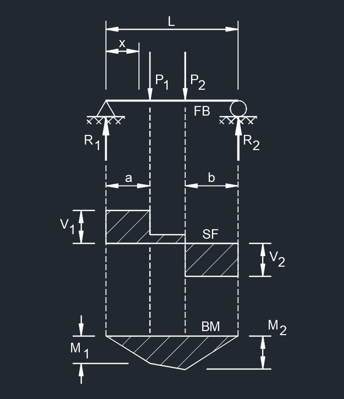 Two Equal Point Loads Unequally Spaced
 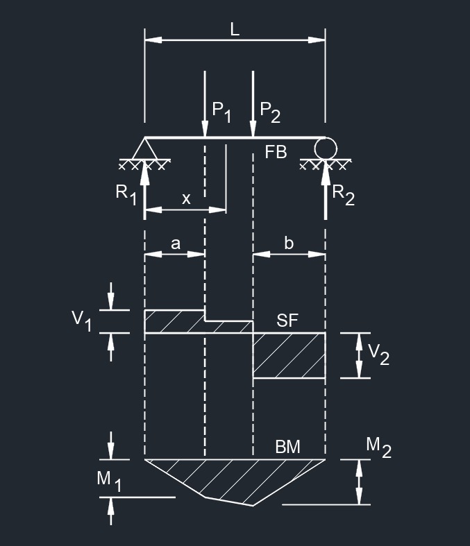 Two Unequal Point Loads Unequally Spaced
 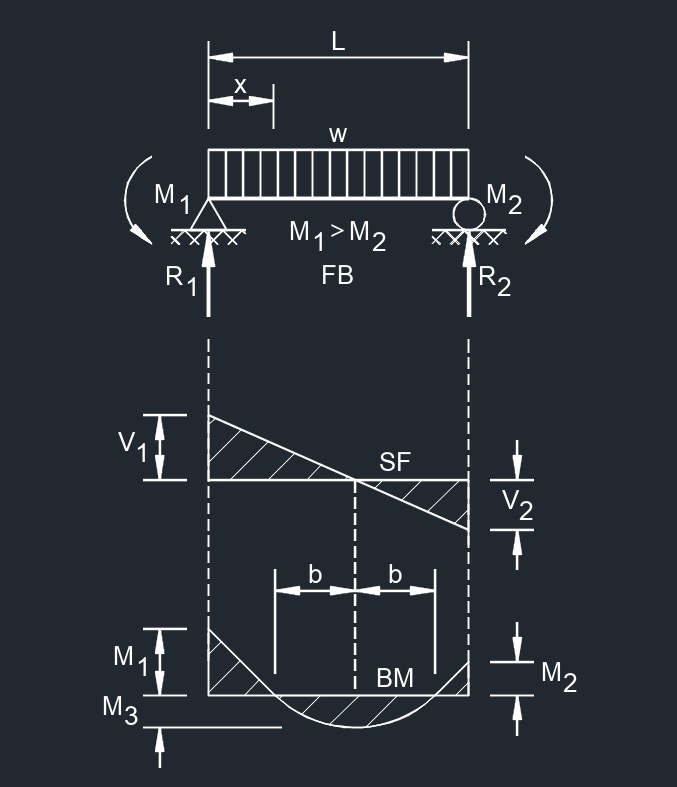 Uniformly Distributed Load and Variable End Moments
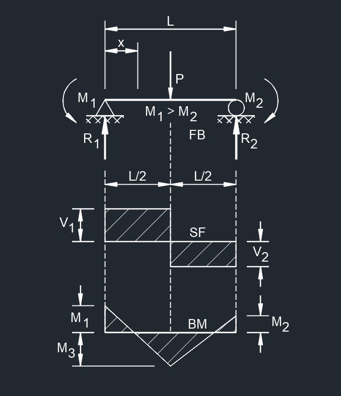 Central Point Load and Variable End Moments
Beam Fixed at One End
Beam Fixed at Both Ends
 Uniformaly Distributed Load
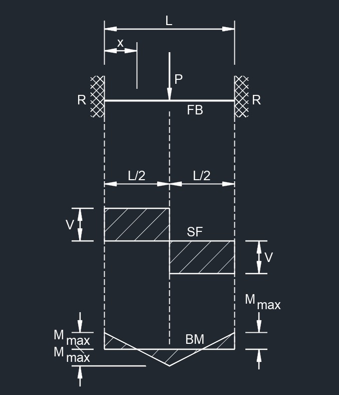 Concentrated Load at Center
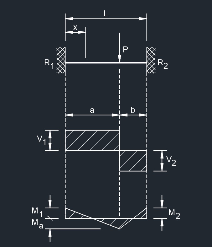 Concentrated Load at Any Point
Cantilever Beam
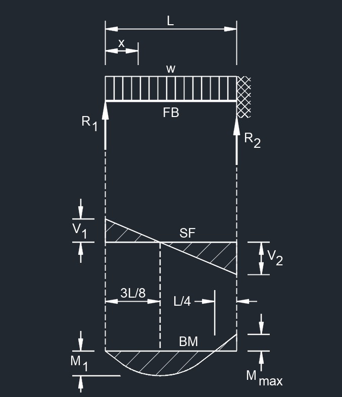
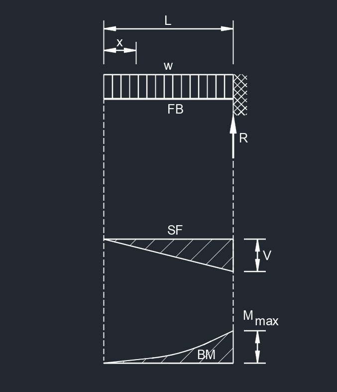 Uniformaly Distributed Load
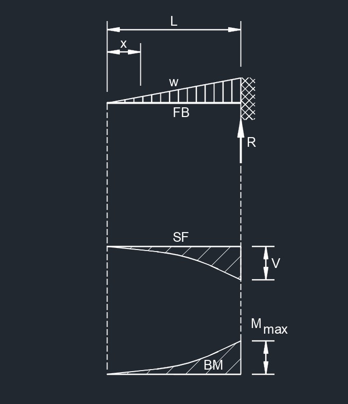 Load Increasing Uniformly to One End
 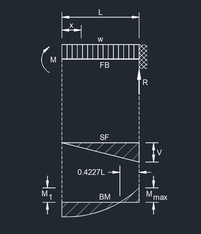 Uniformly Distributed Load and Variable End Moments
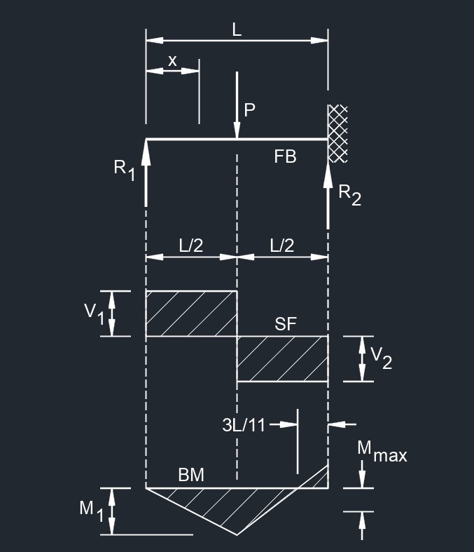
 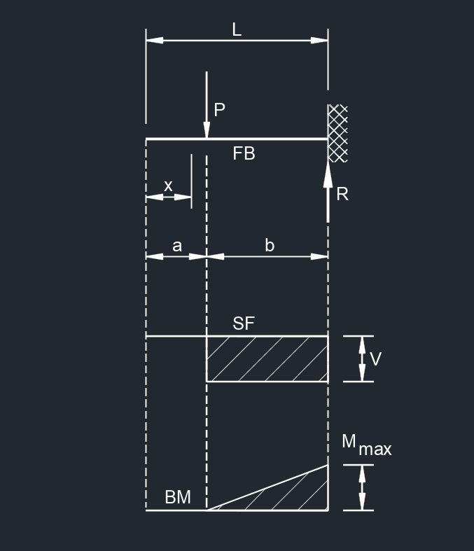 Concentrated Load at Any Point
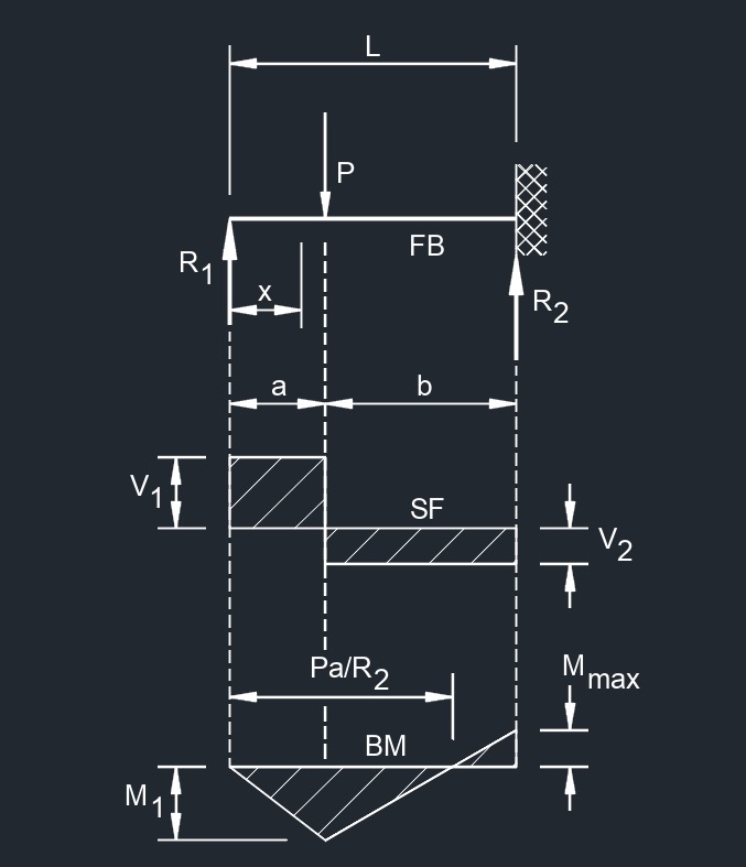
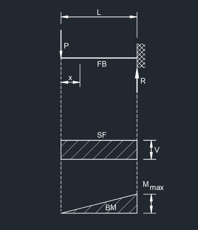 Concentrated Load at Free End
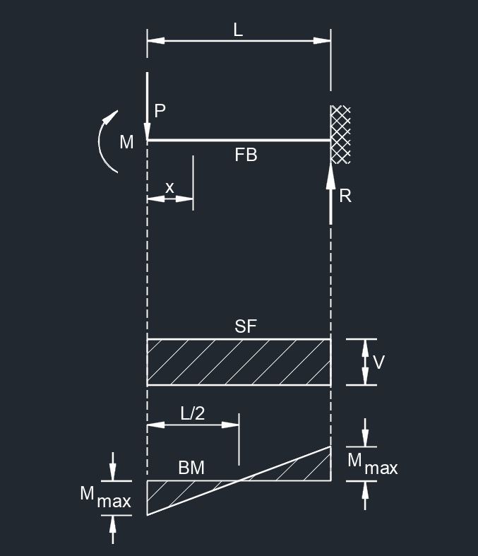 Load at Free End Deflection Vertically with No Rotation
Overhanging Beam
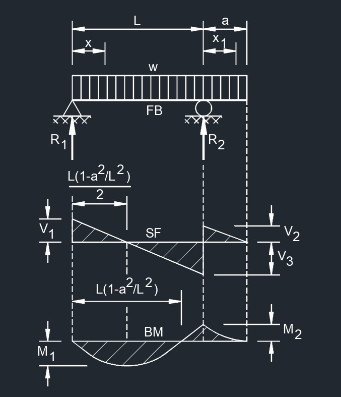 Uniformly Distributed Load
 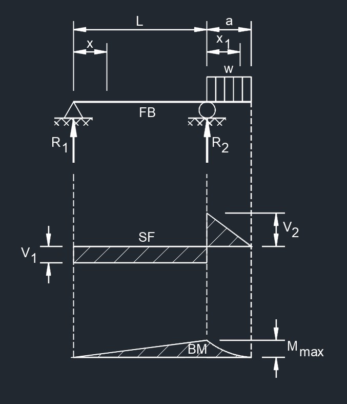 Uniformly Distributed Load on Overhang
 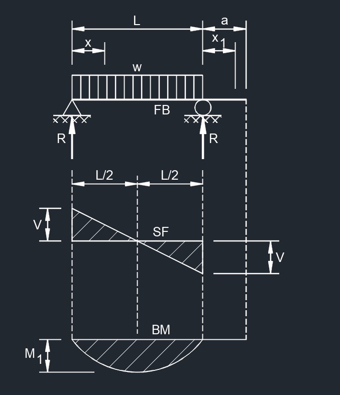 Uniformly Distributed Load Over Supported Span
 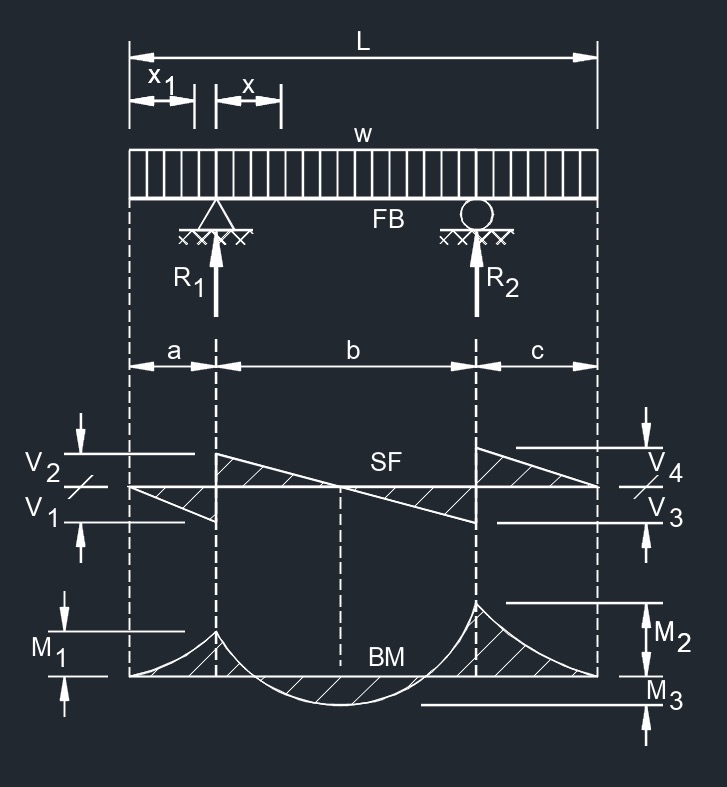 Uniformly Distributed Load Overhanging Both Supports
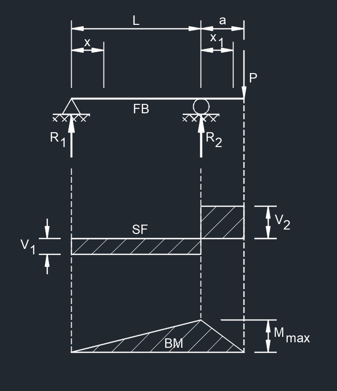 Point Load on Beam End
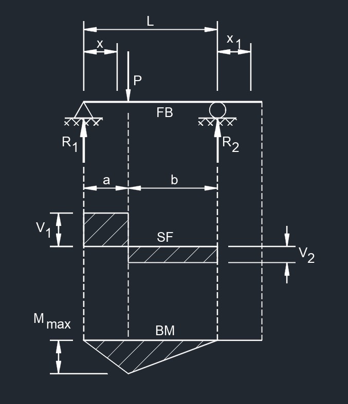 Point Load Between Supports at Any Point
Two Span Continuous Beam
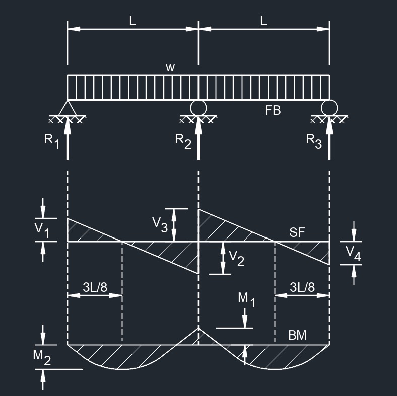 Equal Spans, Uniformly Distributed Load
 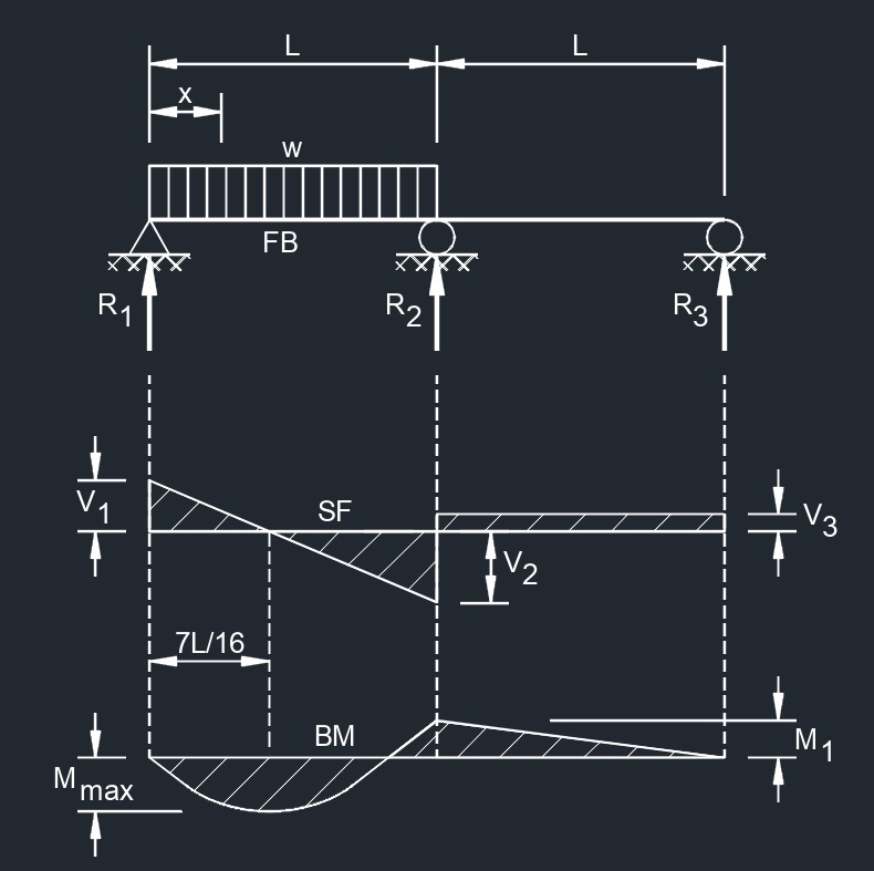 Equal Spans, Uniform Load on One Span
 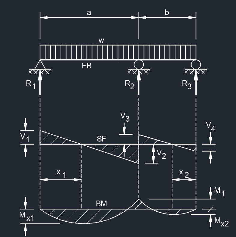 Unequal Spans, Uniformly Distributed Load
 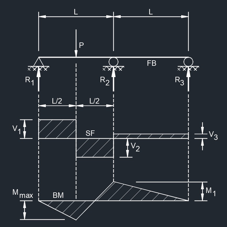 Equal Spans, Concentrated Load at Center of One Span
 Equal Spans, Two Equal Concentrated Loads Symmetrically Placed
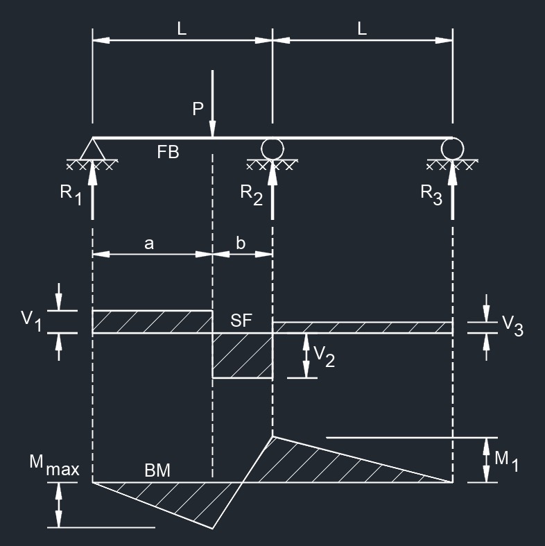 Equal Spans, Concentrated Load at Any Point
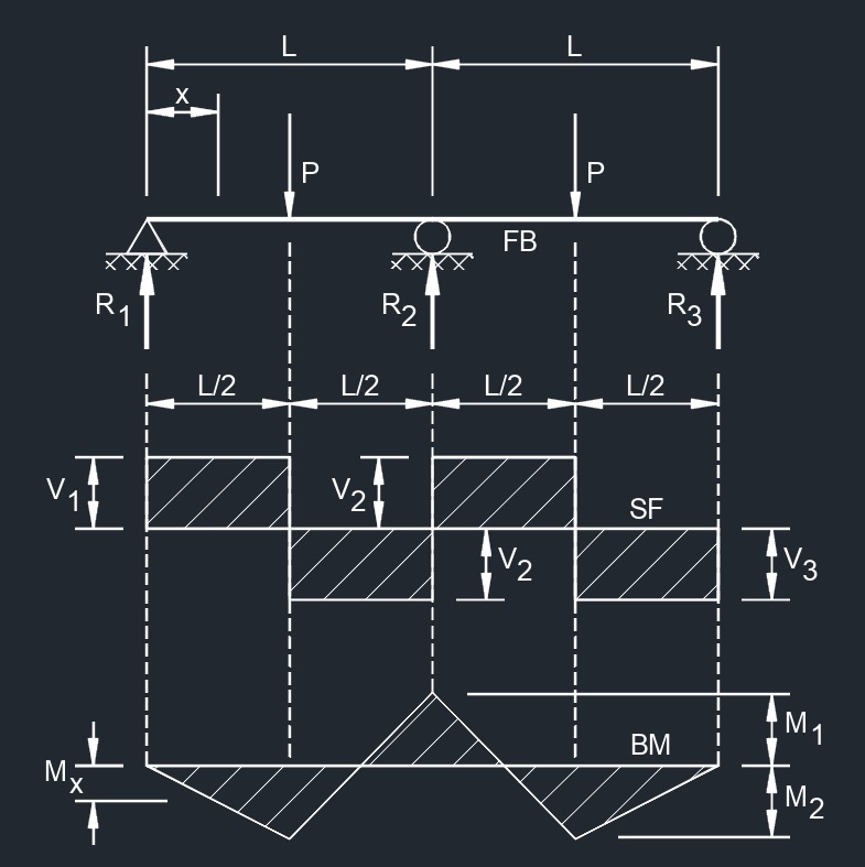
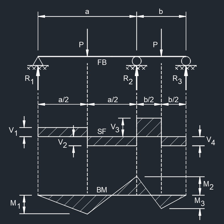 Unequal Spans, Concentrated Load on Each Span Symmetrically Placed
Three Span Continuous Beam
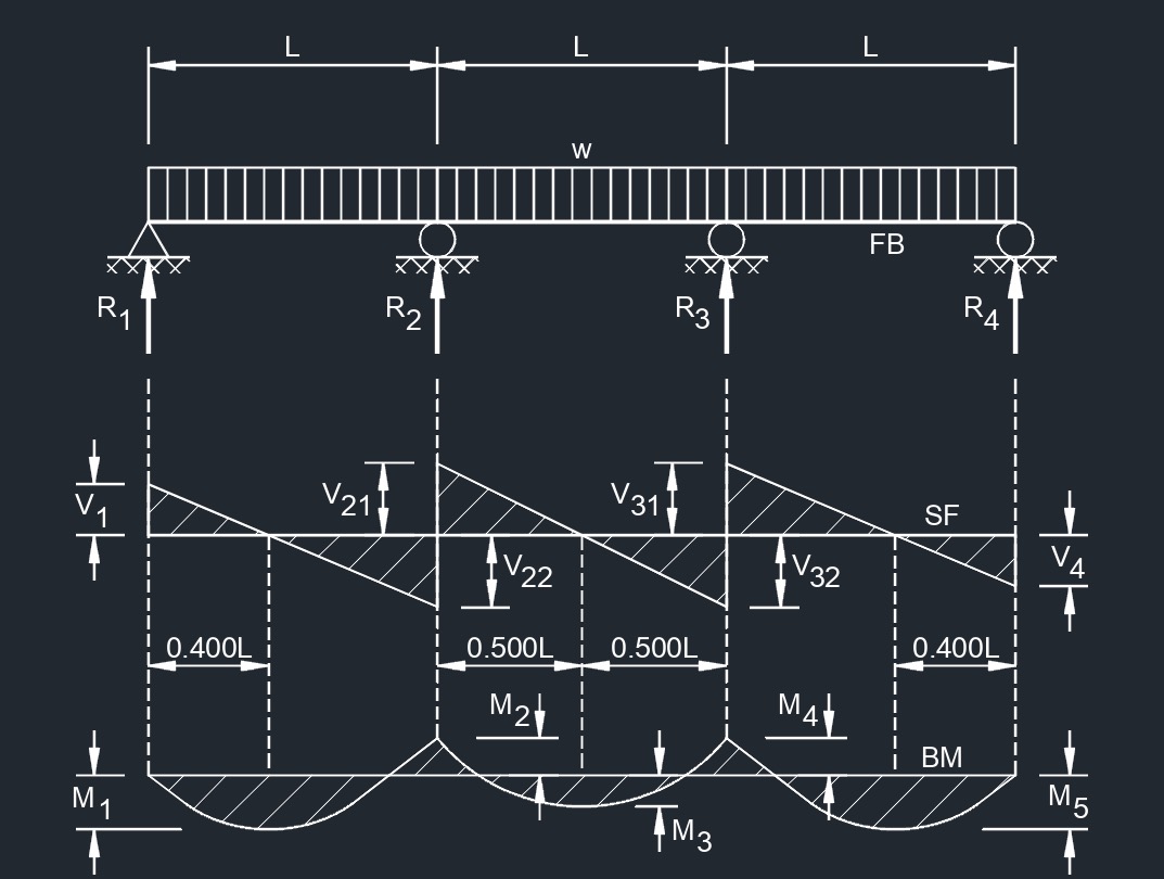 Equal Spans, Uniformly Distributed Load
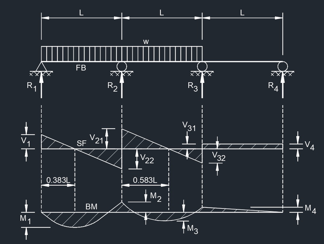 Equal Spans, Uniform Load on Two Spans to One Side
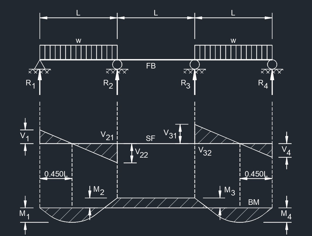 Equal Spans, Uniform Load on Two Spans at Each End
Four Span Continuous Beam
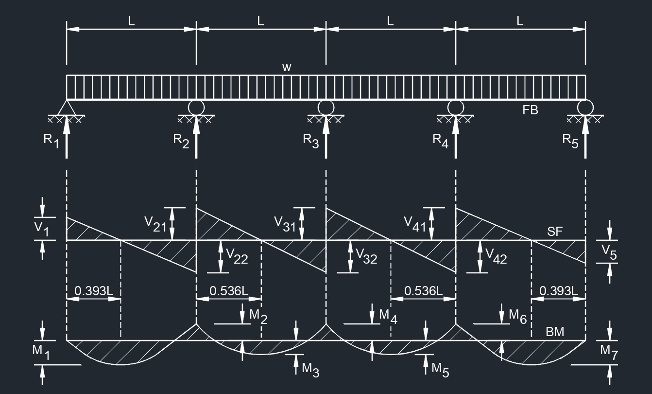 Equal Spans, Uniformly Distributed Load
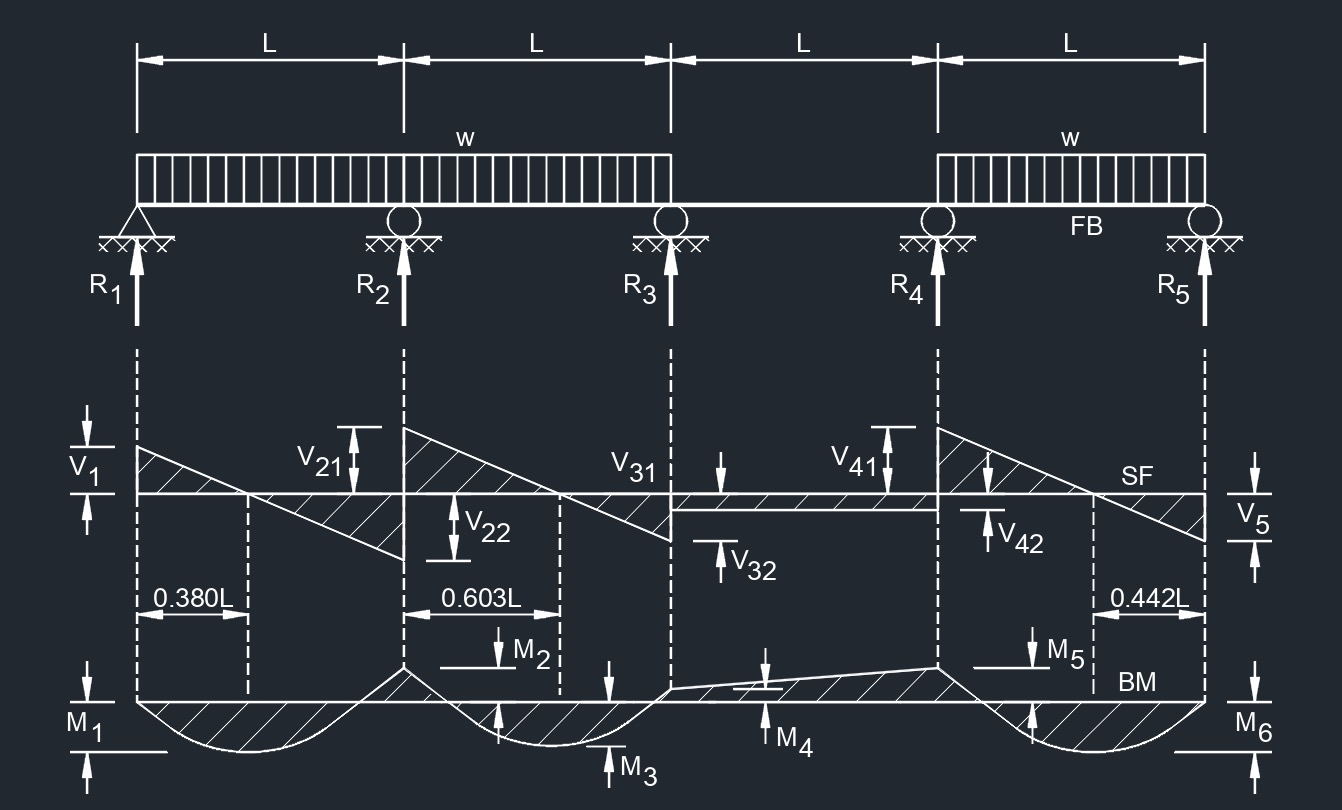 Equal Spans, Uniform Load on Three Spans
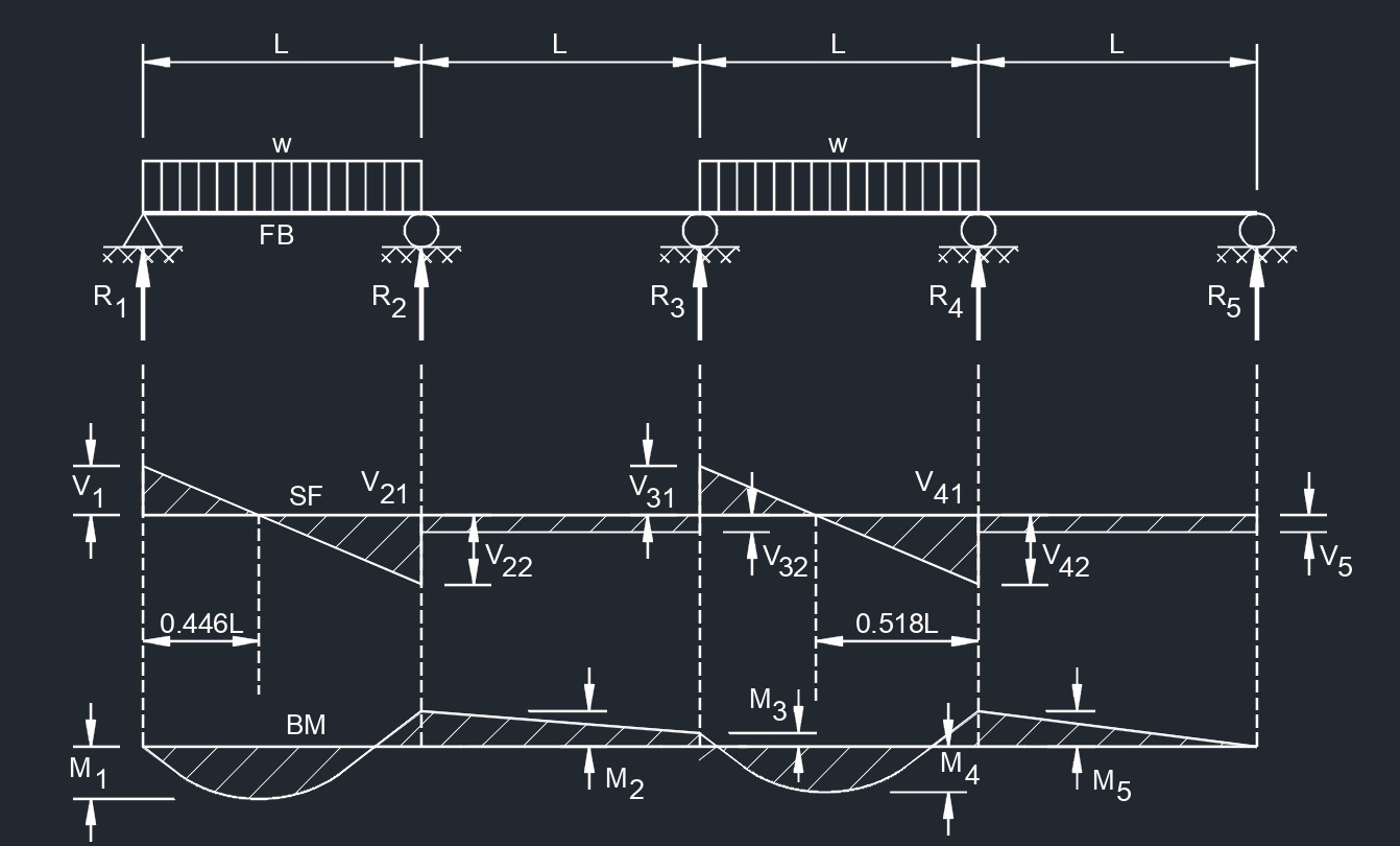 Equal Spans, Uniform Load on Two Spans
Nomenclature, Symbols, and Units for Beam Supports |
||||||
| Symbol | Greek Symbol | Definition | English | Metric | SI | Value |
| \(\Delta\) | Delta | deflection or deformation | \(in\) | \(mm\) | \(mm\) | - |
| \(a, b\) | - | distance to point load | \(in\) | \(mm\) | \(mm\) | - |
| \(w\) | - | highest load per unit length | \(lbf\;/\;in\) | \(N\;/\;m\) | \(N-m^{-1}\) | |
| \(x\) | - | horizontal distance from reaction to point on beam | \(in\) | \(mm\) | \(mm\) | - |
| \(w\) | - | load per unit length | \(lbf\;/\;in\) | \(N\;/\;m\) | \(N-m^{-1}\) | - |
| \(M\) | - | maximum bending moment | \(lbf-in\) | \(N-mm\) | \(N-mm\) | - |
| \(V\) | - | maximum shear force | \(lbf\) | \(N\) | \(kg-m-s^{-2}\) | |
| \(\lambda\) | lambda | modulus of elasticity | \(lbf\;/\;in^2\) | \(MPA\) | \(N-mm^{-2}\) | - |
| \(R\) | - | reaction load at bearing point | \(lbf\) | \(N\) | \(kg-m-s^{-2}\) | - |
| \(I\) | - | second moment of area (moment of inertia) | \(in^4\) | \(mm^4\) | \(mm^4\) | - |
| \(L\) | - | span length of the bending member | \(in\) | \(mm\) | \(mm\) | - |
| \(P\) | - | total concentrated load | \(lbf\) | \(N\) | \(kg-m-s^{-2}\) | - |
| \(W\) | - | total load \(\left( \frac{w\;L}{2} \right)\) | \(lbf\) | \(N\) | \(kg-m-s^{-2}\) | - |