|
See Articles
|
See Articles
|
Two Member Frame - Fixed/Fixed
 Top Point Load
 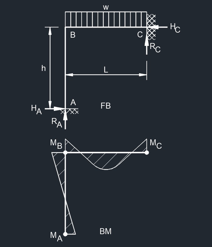 Top Uniformaly Distributed Load
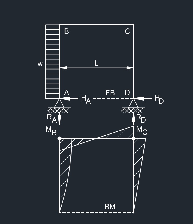
Two Member Frame - Fixed/Free
 Free End Horizontal Point Load
 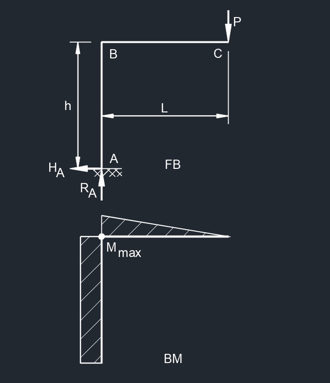 Free End Vertical Point Load
 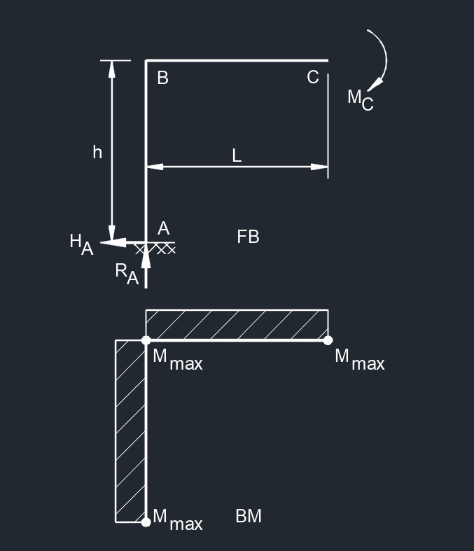 Free End Bending Moment
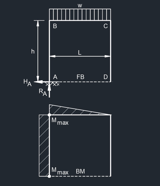
 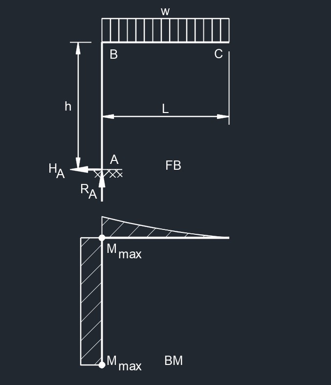 Top Uniformaly Distributed Load
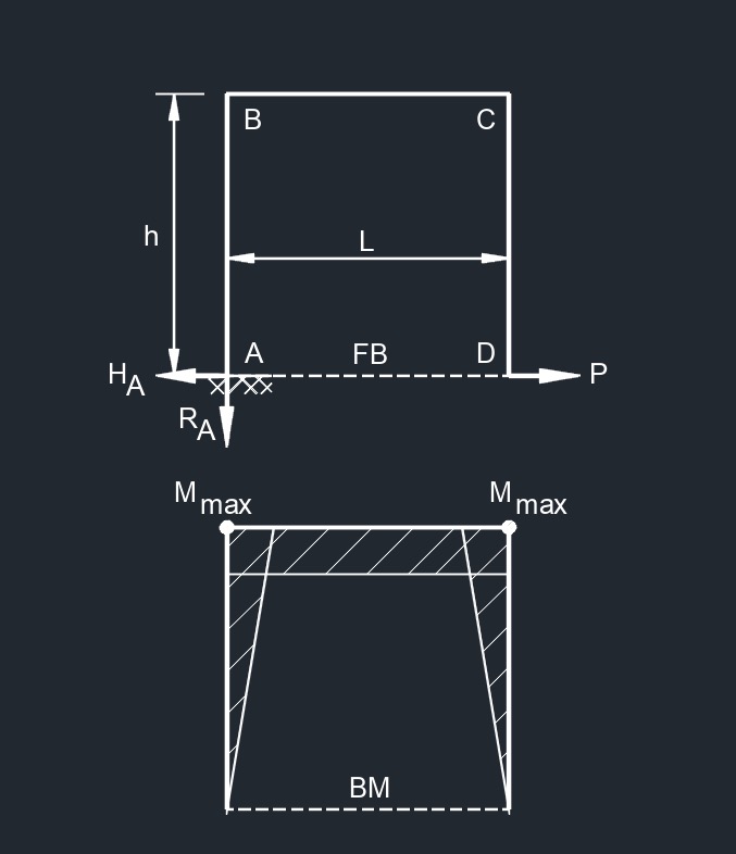
Two Member Frame - Fixed/Pin
 Top Point Load
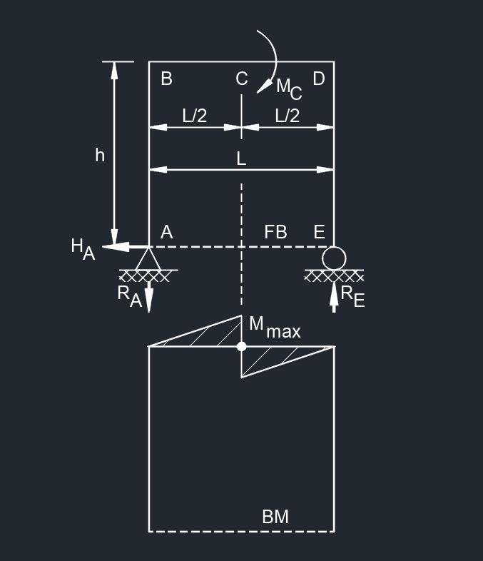
 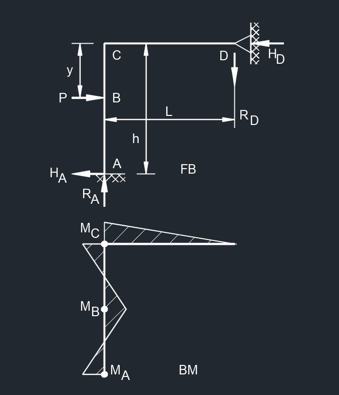 Side Point Load
 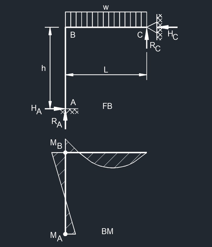 Top Uinformaly Distributed Load
 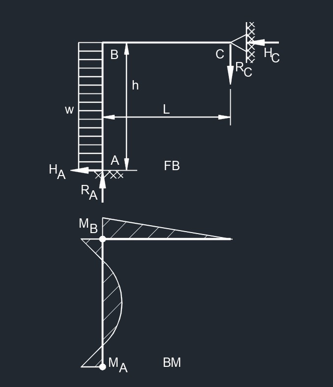 Side Uniformaly Distributed Load
Two Member Frame - Pin/Pin
 Top Ppint Load
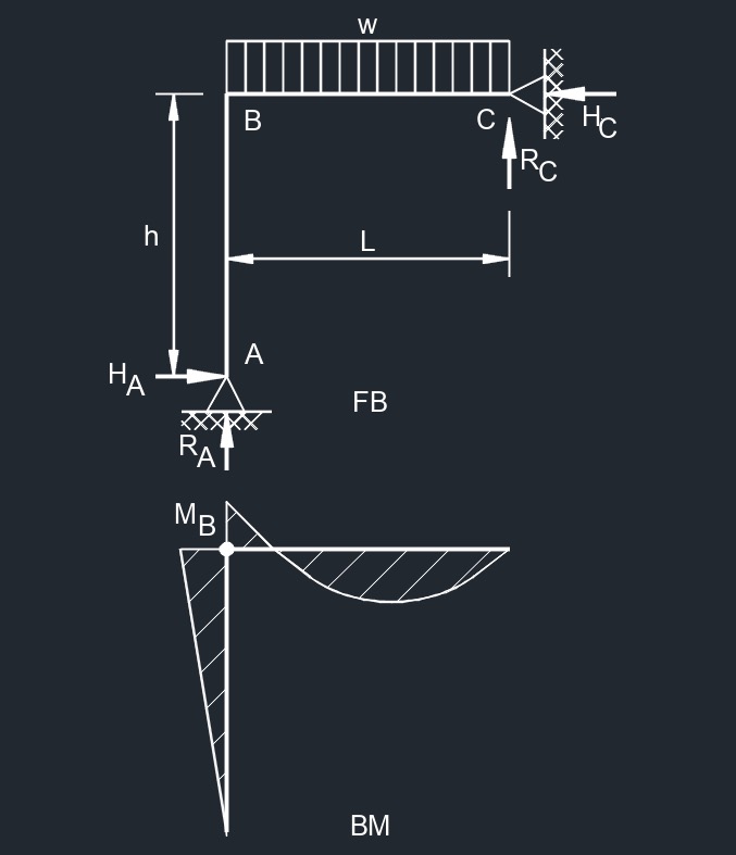 Top Uniformaly Distributed Load
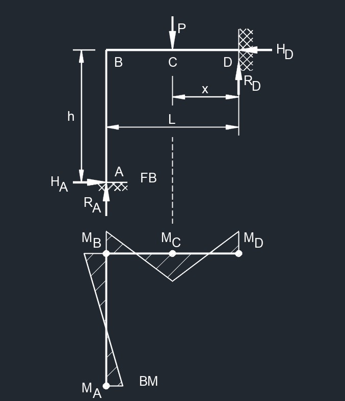
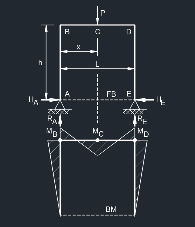
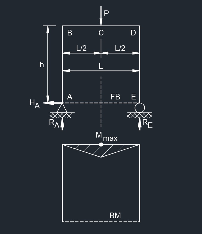
Three Member Frame - Fixed/Fixed
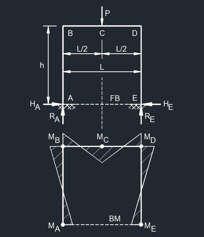 Center Point Load
 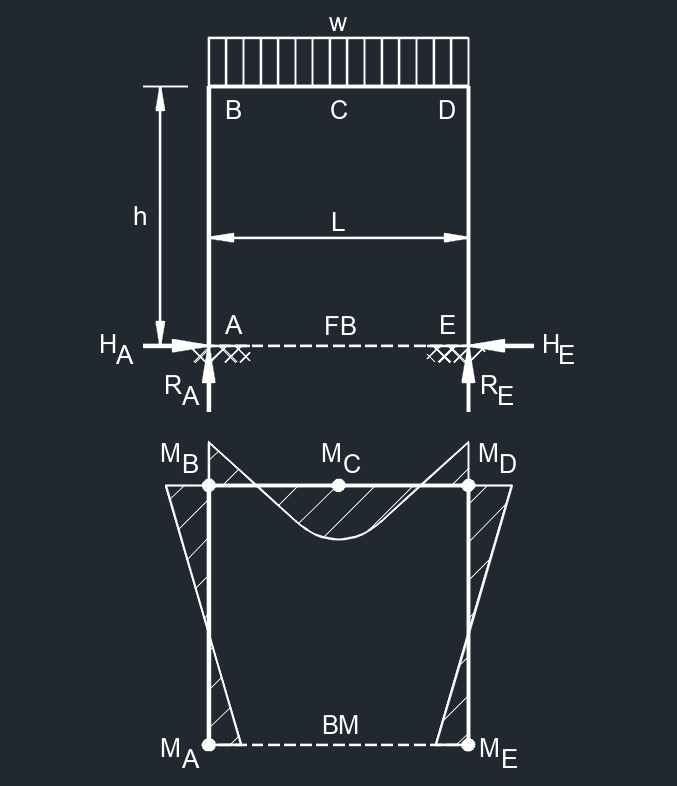 Top Uniformaly Distributed Load
 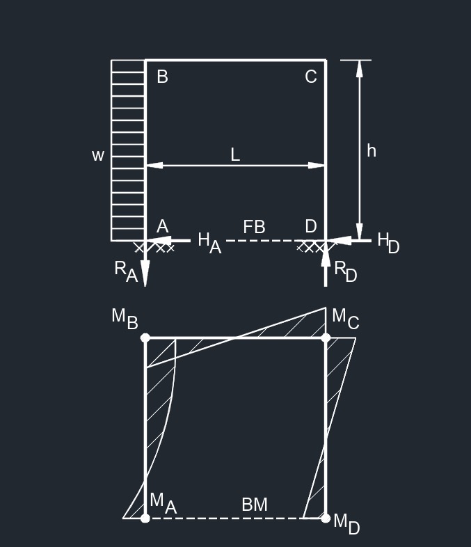 Side Uniformaly Distributed Load
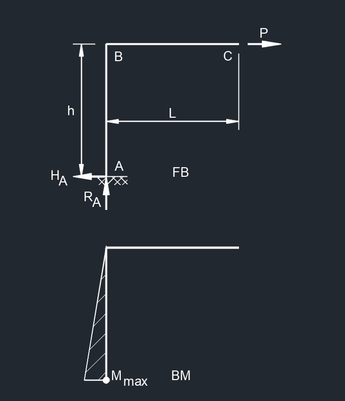
Three Member Frame - Fixed/Free
 Free End Horizontal Point Load
 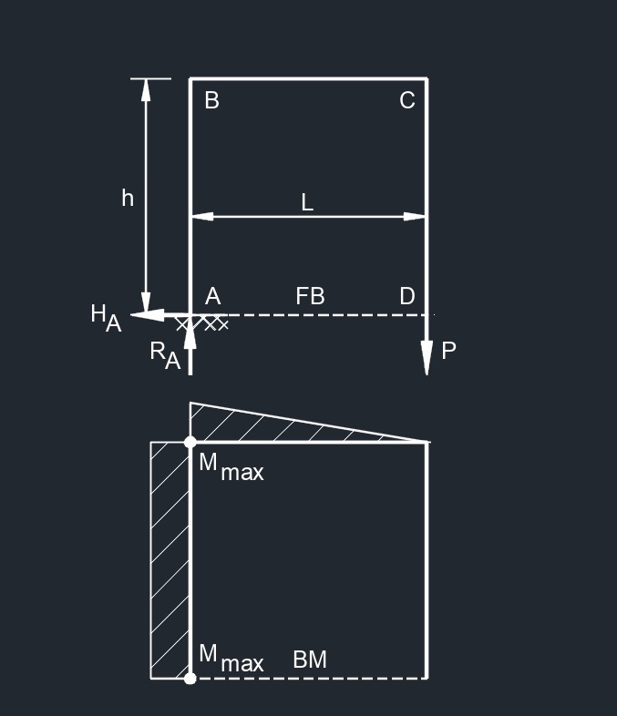 Free End Vertical Point Load
 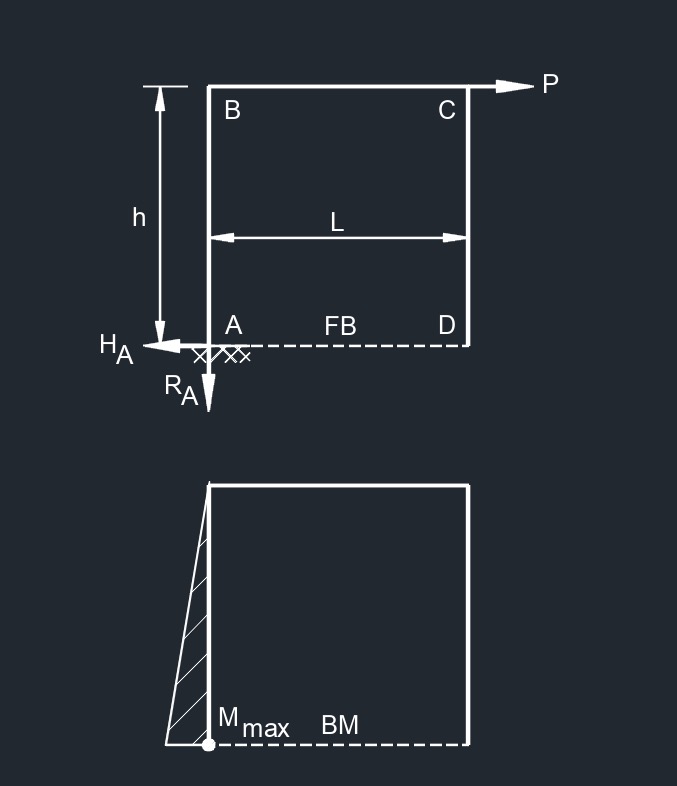 Side Top Point Load
 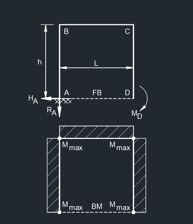 Free End Bending Moment
 Top Uniformaly Distributed Load
Three Member Frame - Pin/Pin
 Top Point Load
 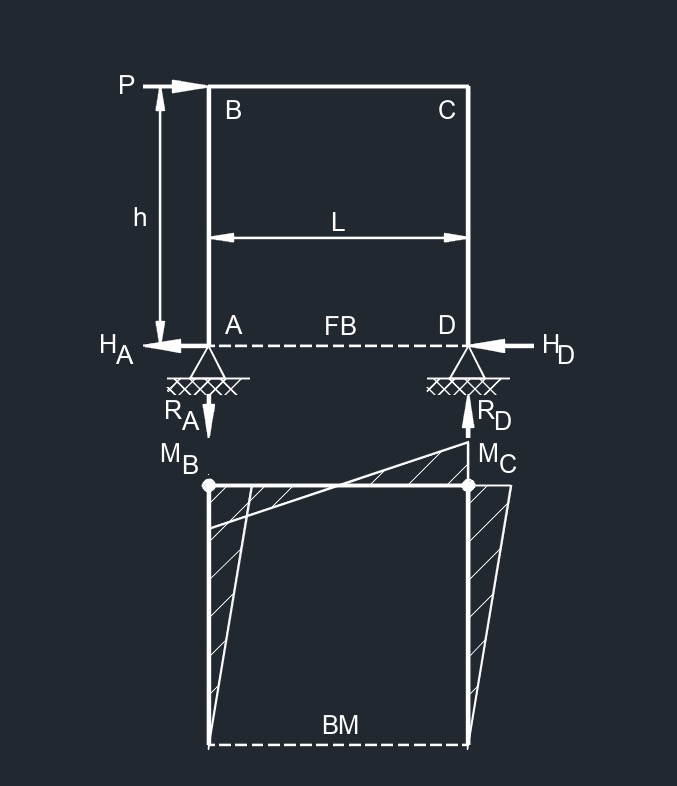 Top Horizontal Point Load
 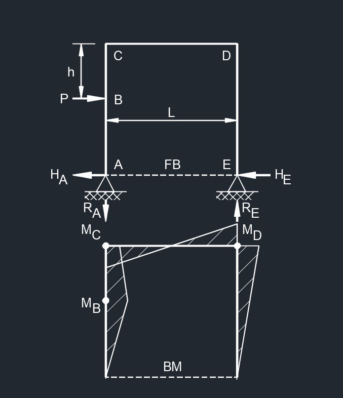 Side Point Load
 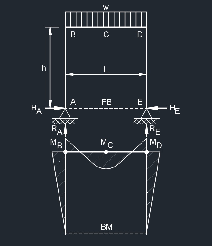 Top Uniformaly Distributed Load
 Side Uniformaly Distributed Load
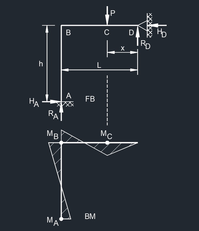
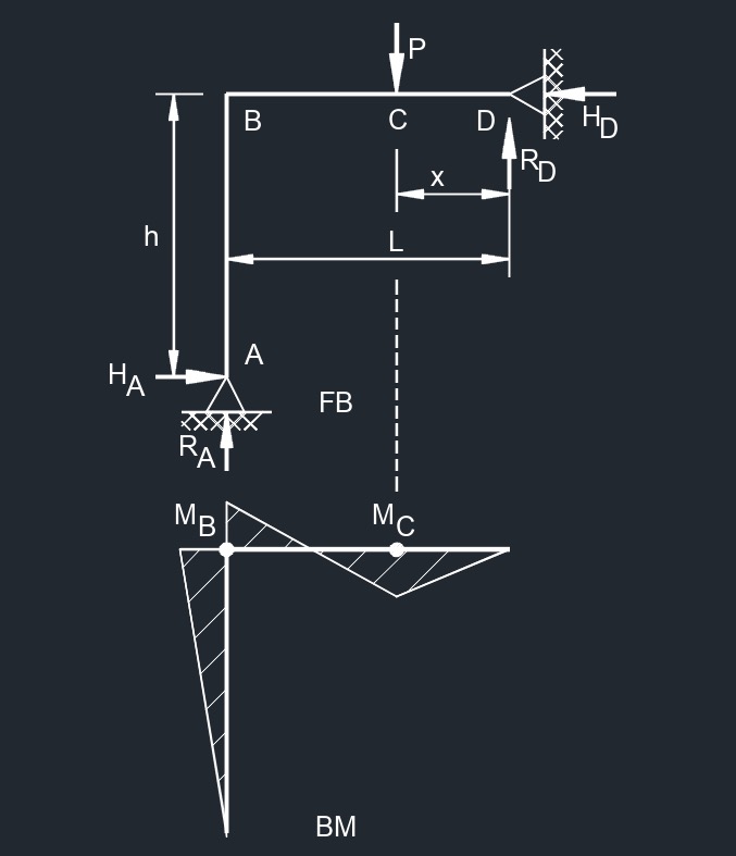
Three Member Frame - Pin/Roller
 Center Point Load
 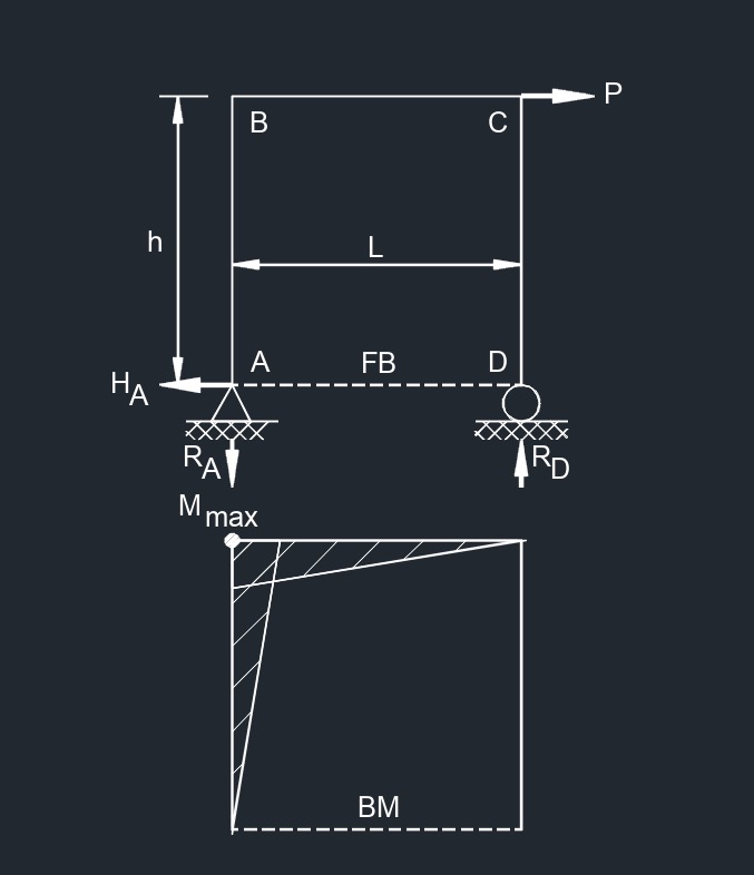 Side and Top Point Load
 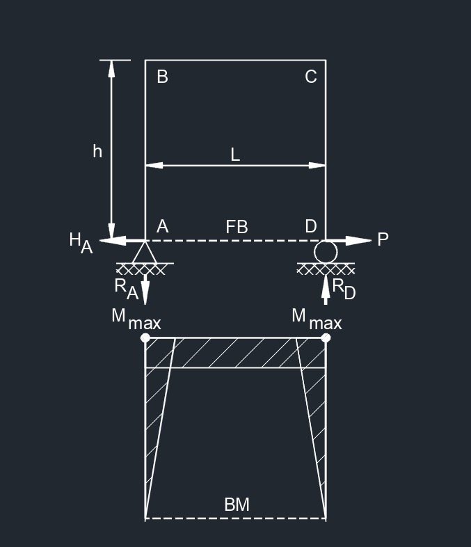 Side and Bottom Point Load
 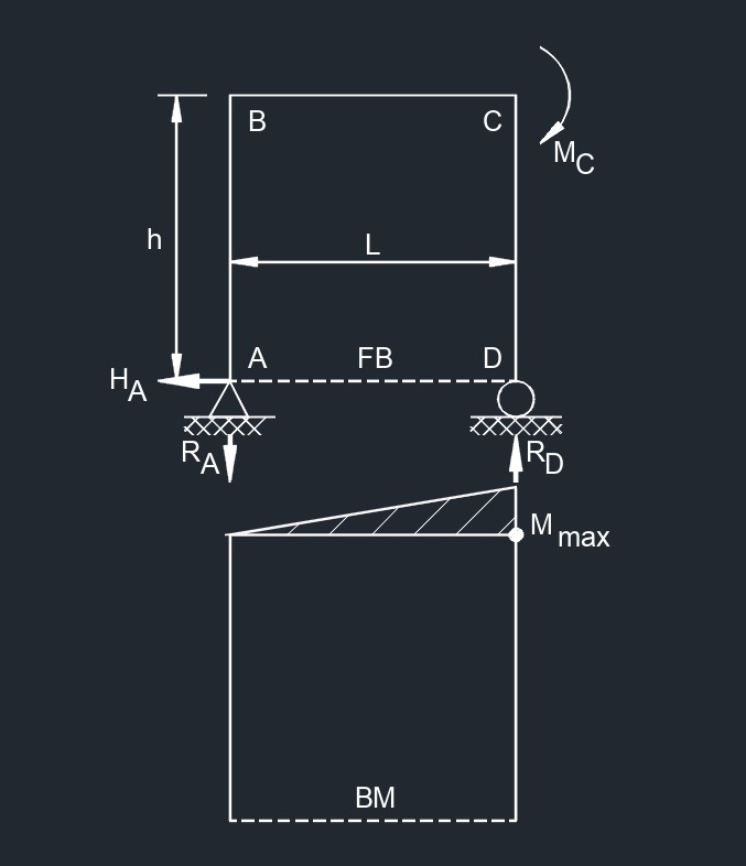 Side and Top Bending Moment
 Central Bending Moment
 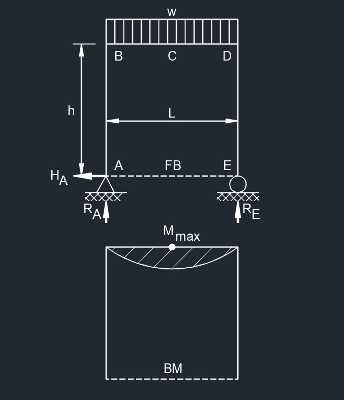 Top Uniformaly Distributed Load
 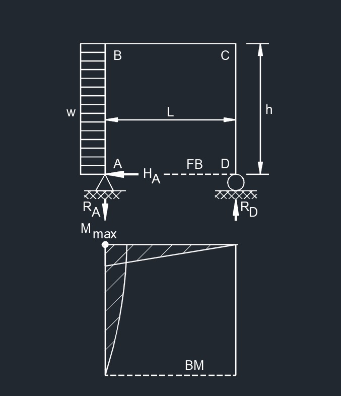 Side Uniformaly Distributed Load
 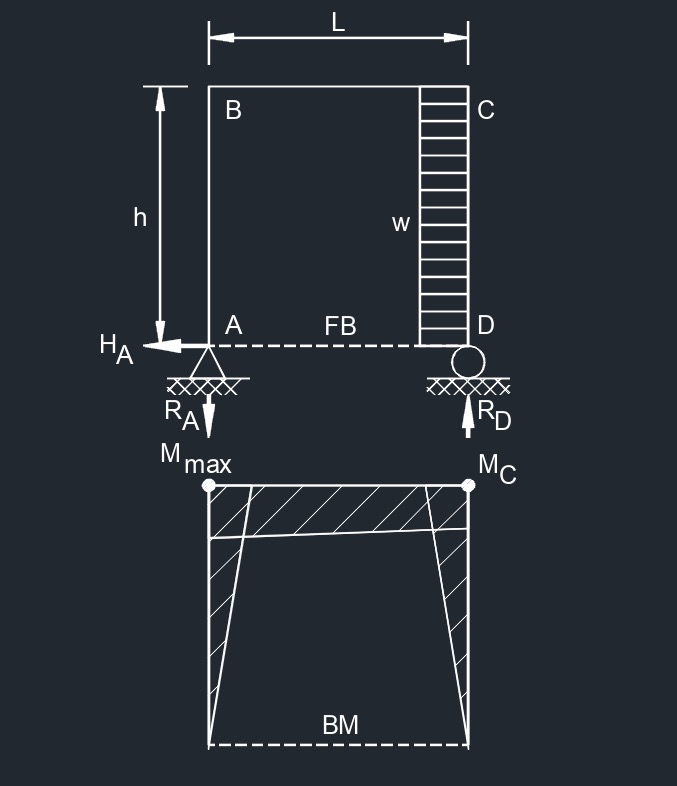 Outer Side Uniformaly Distributed Load
Nomenclature, Symbols, and Units for Frame Supports |
||||||
| Symbol | Greek Symbol | Definition | English | Metric | SI | Value |
| \(\Delta\) | Delta | deflection or deformation | \(in\) | \(mm\) | \(mm\) | - |
| \(h\) | - | height of frame | \(in\) | \(mm\) | \(mm\) | - |
| \(x\) | - | horizontal distance from reaction point | \(in\) | \(mm\) | \(mm\) | - |
| \(H\) | - | horizontal reaction load at bearing point | \(lbf\) | \(N\) | \(kg-m-s^{-2}\) | - |
| \(I_h\) | - | horizontal member second moment of area (moment of inertia) | \(in^4\) | \(mm^4\) | \(mm^4\) | - |
| \(w\) | - | load per unit length | \(\large{\frac{lbf}{in}}\) | \(\large{\frac{N}{m}}\) | \(N-m^{-1}\) | - |
| \(M\) | - | maximum bending moment | \(lbf-in\) | \(N-mm\) | \(N-mm\) | - |
| \(\lambda\) | lambda | modulus of elasticity | \(\large{\frac{lbf}{in^2}}\) | \(MPA\) | \(N-mm^{-2}\) | - |
| \(A, B, C, D, E\) | - | point of intrest on frame | - | - | - | - |
| \(L\) | - | span length under consideration | \(in\) | \(mm\) | \(mm\) | - |
| \(P\) | - | total concentrated load | \(lbf\) | \(N\) | \(kg-m-s^{-2}\) | - |
| \(I_v\) | - | vertical member second moment of area (moment of inertia) | \(in^4\) | \(mm^4\) | \(mm^4\) | - |
| \(R\) | - | vertical reaction load at bearing point | \(lbf\) | \(N\) | \(kg-m-s^{-2}\) | - |
![]()