Welding symbols are graphical representations used in engineering and construction to convey information about the welding process and requirements for joining metal components. These symbols are standardized and follow guidelines established by organizations like the American Welding Society (AWS) and the International Organization for Standardization (ISO).
Welding symbols are typically included in engineering drawings and blueprints to provide welders, inspectors, and other stakeholders with clear and concise information about the type of weld, its dimensions, location, and other essential details. These symbols help ensure consistency and accuracy in the welding process.
|
See Articles
|
See Articles
|
Welding symbols play a crucial role in ensuring that welding processes are accurately understood and executed according to design specifications. They facilitate effective communication between design engineers, welders, and quality control personnel, ultimately leading to properly welded joints that meet the required standards for strength, integrity, and appearance.
Weld Symbols
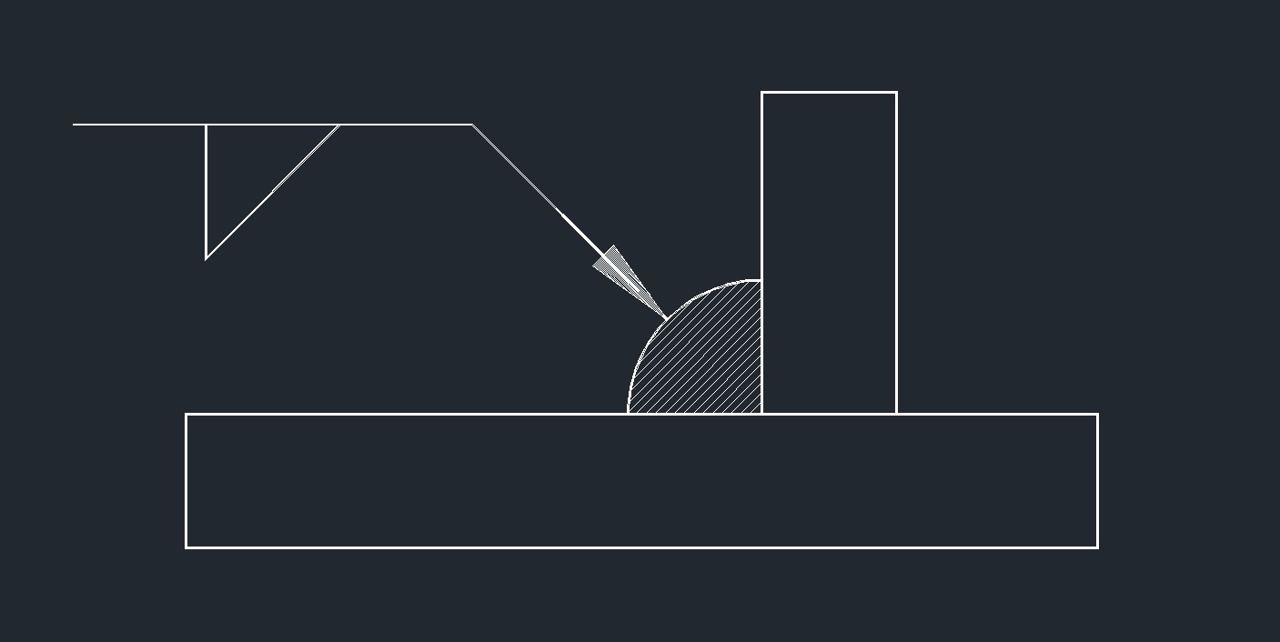 Fillet
 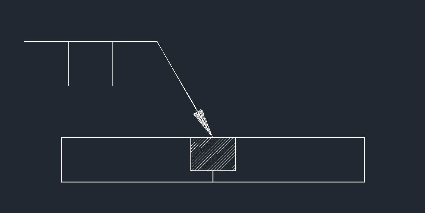 Square Groove
 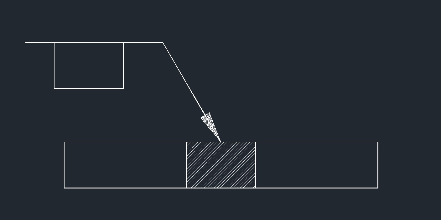 Plug or Slot
 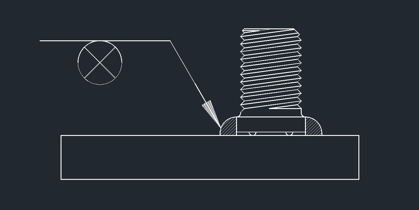 Stud
Stud
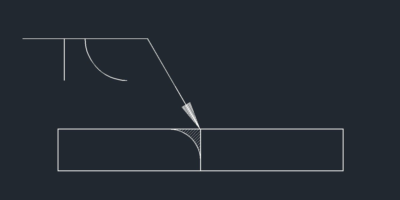 Flare Bevel
 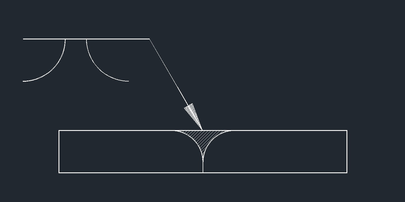 Flare Groove
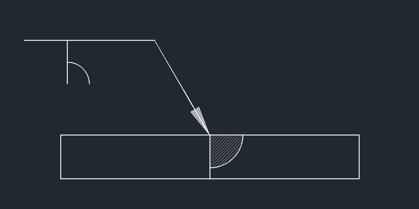
 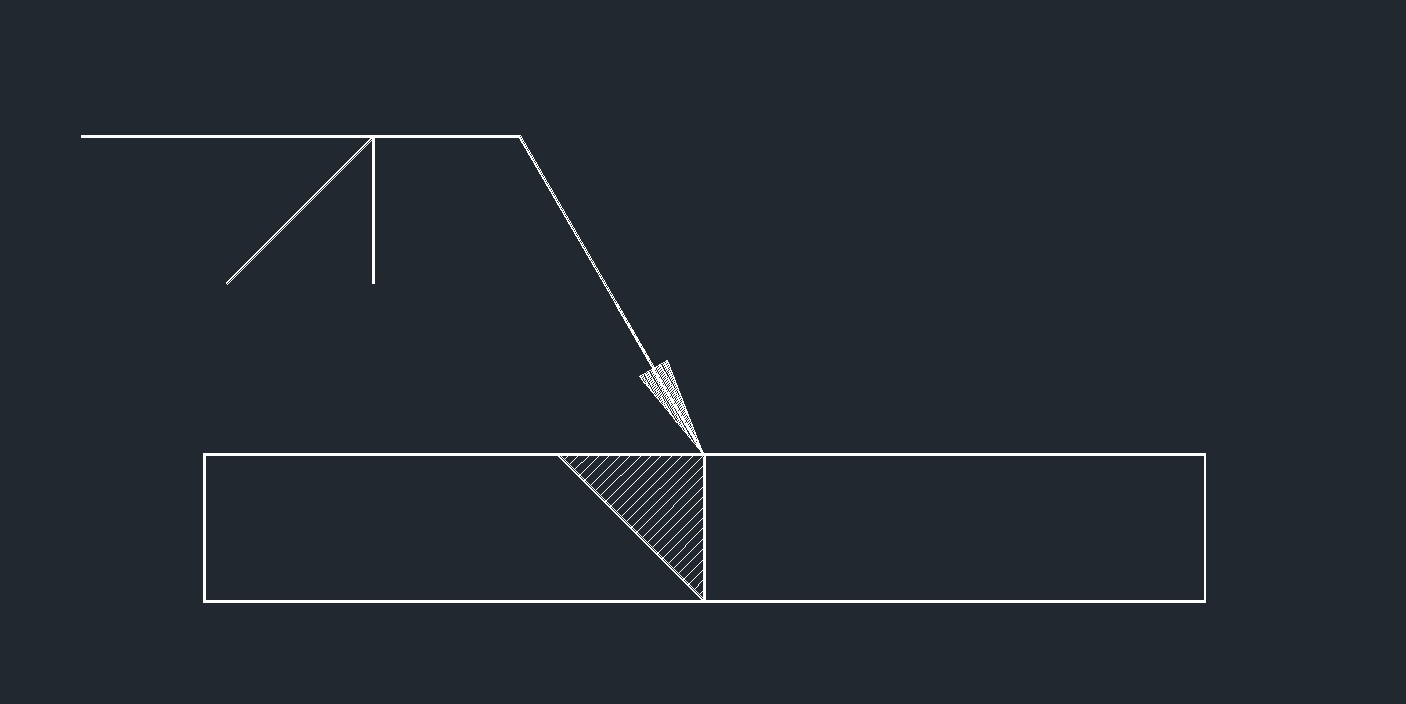 Bevel Groove
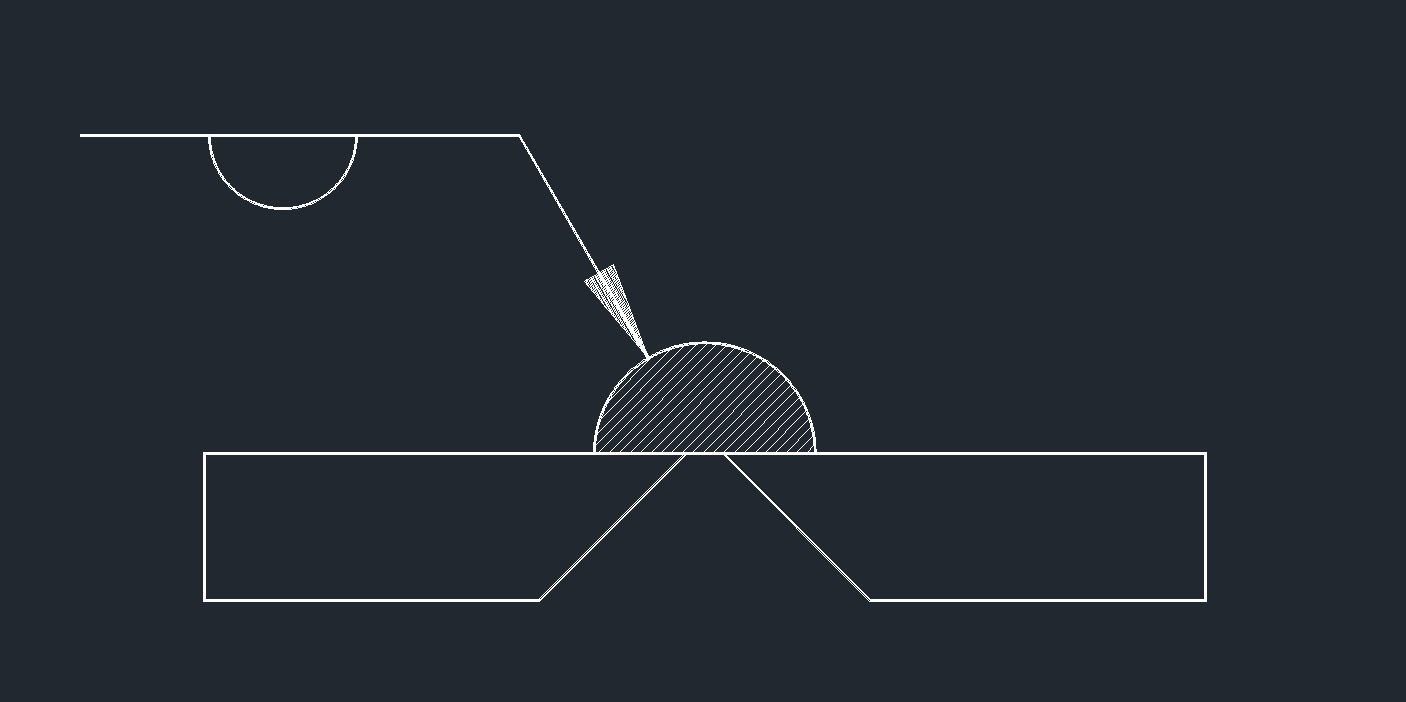
 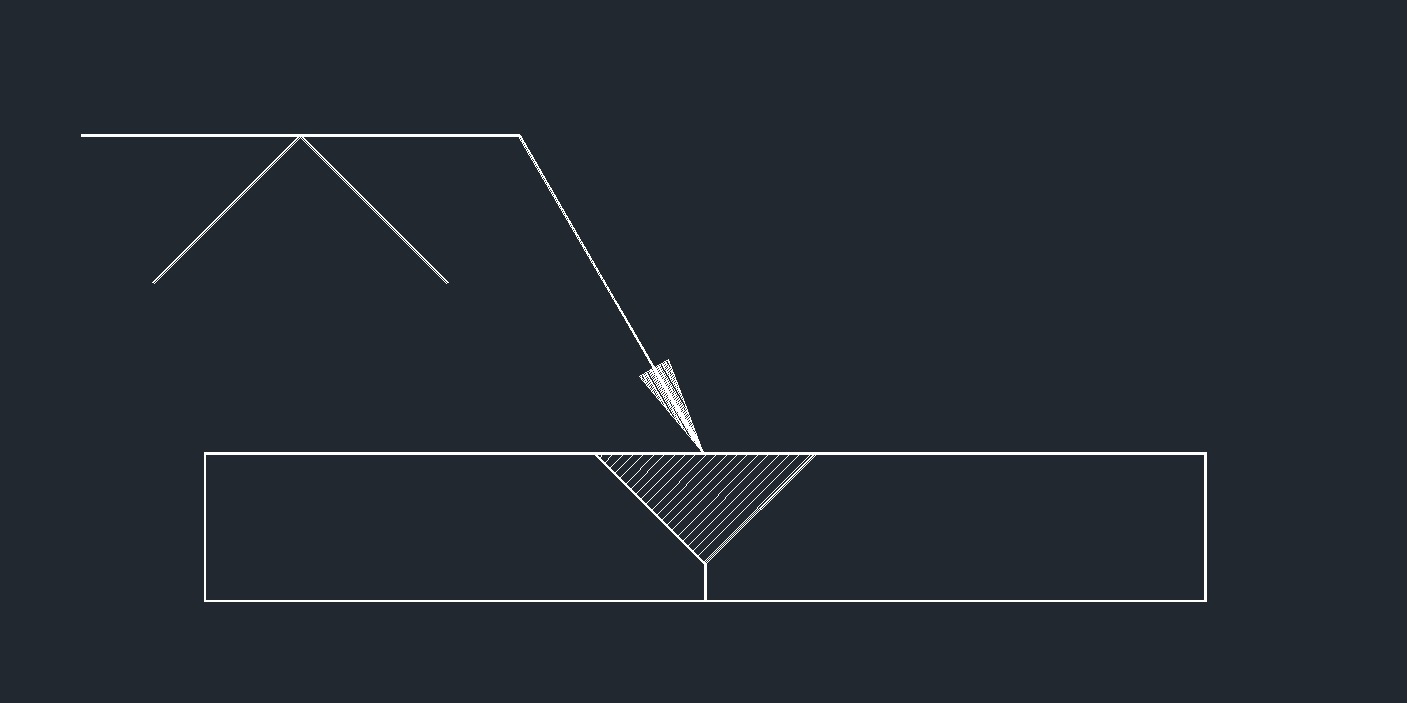 V Groove
 J Groove
 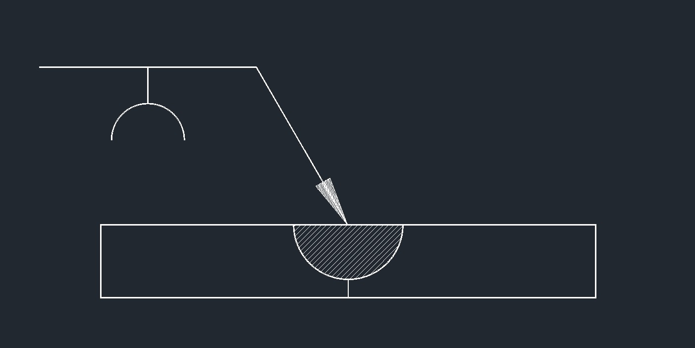 U Groove
 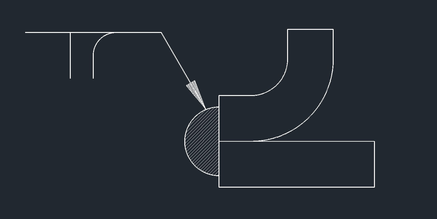 Flange Corner
 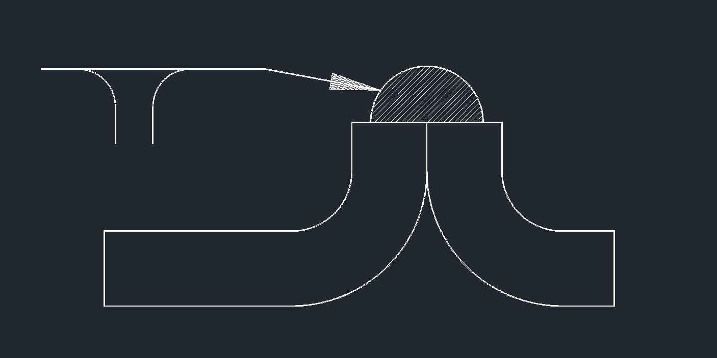 Flange Edge
 Back of Backing
 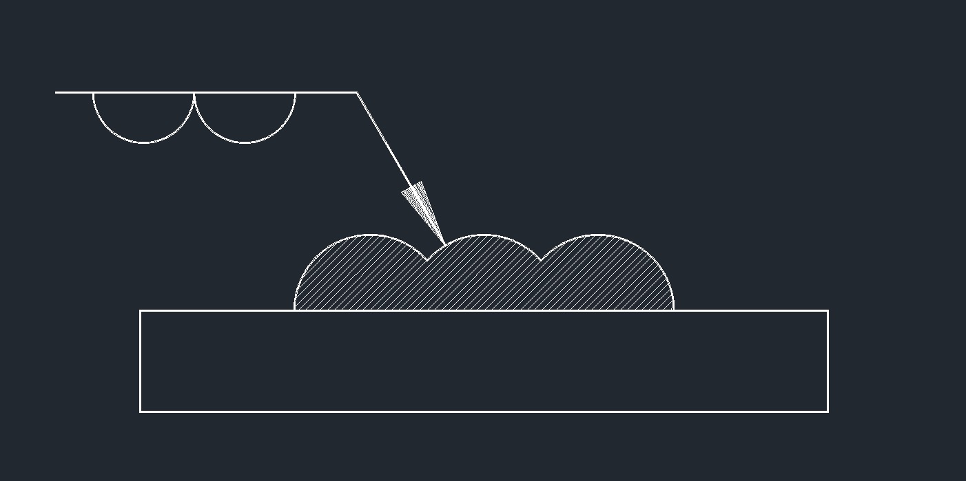 Surfacing
 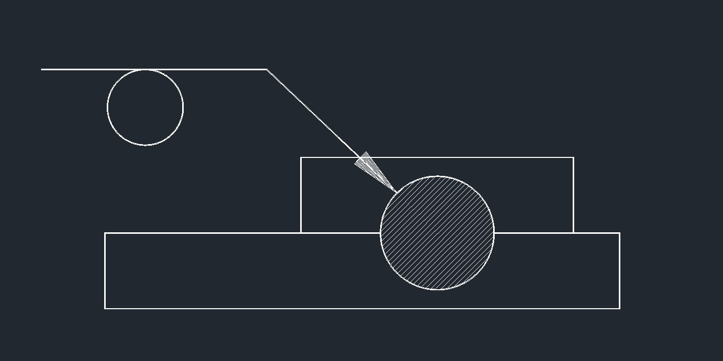 Spot or Projection
 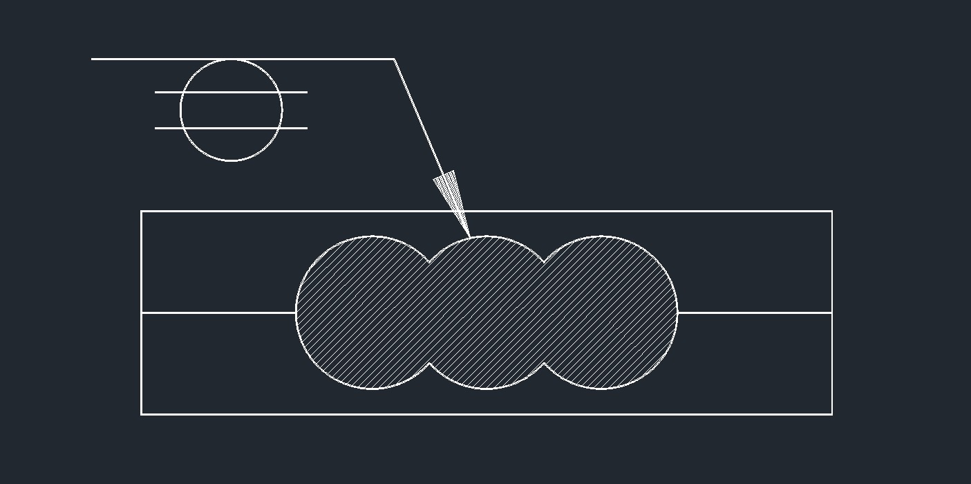 Seam
Seam
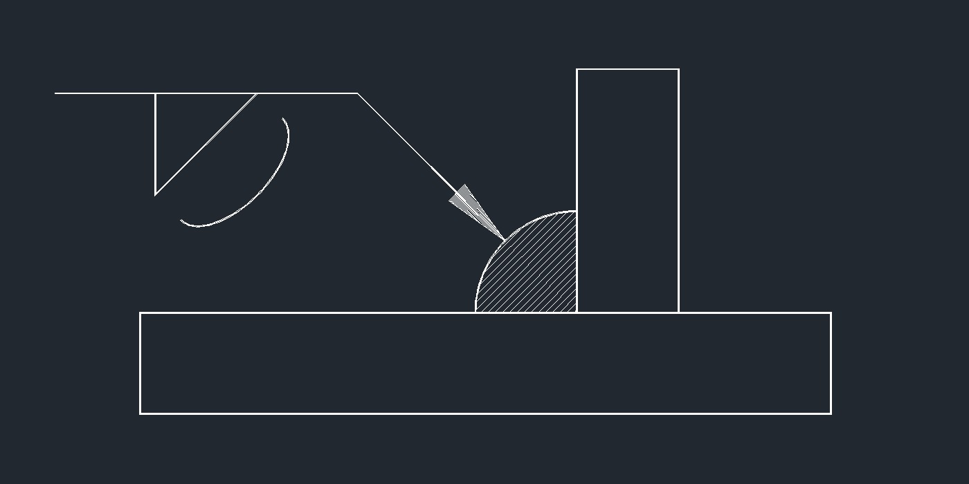
Fillet Weld Symbols
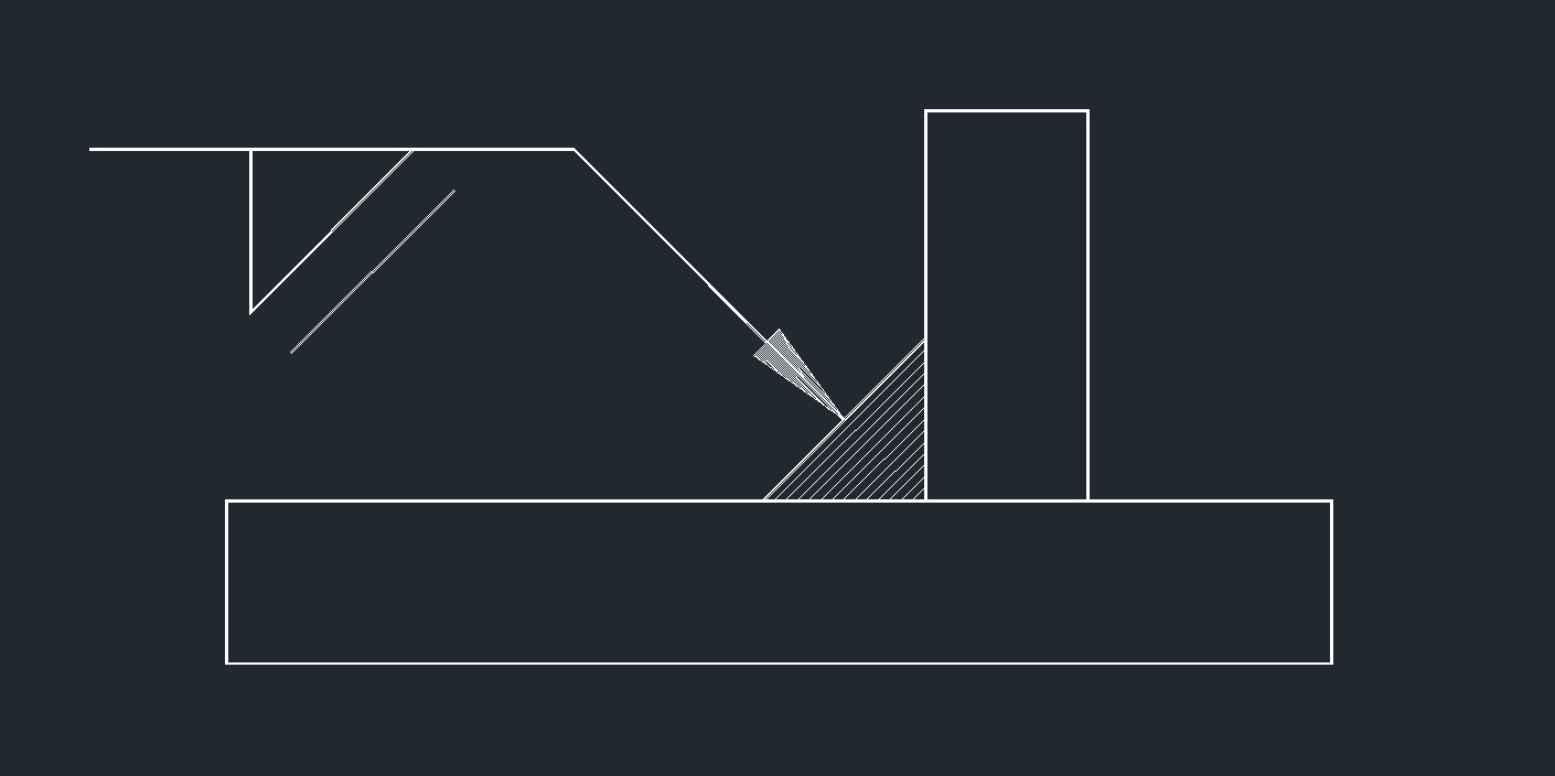 Miter Contour Fillet
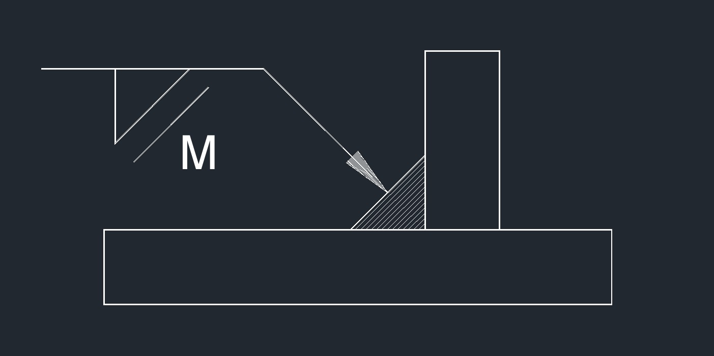 Miter Machining Fillet
 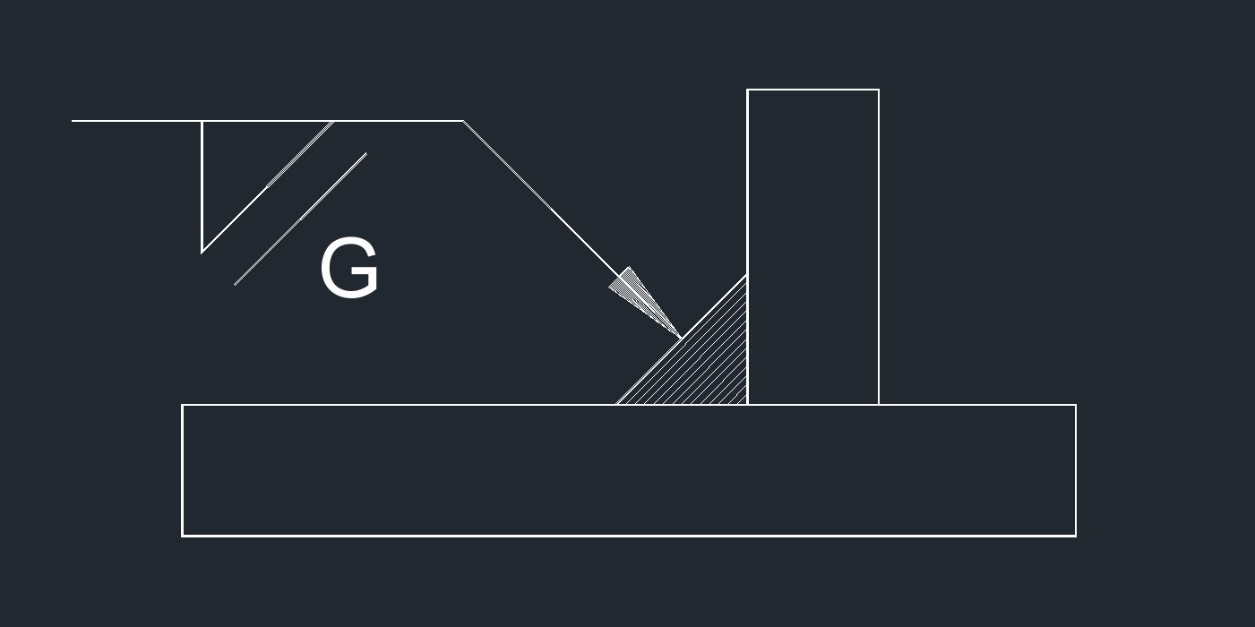 Miter Grinding Fillet
 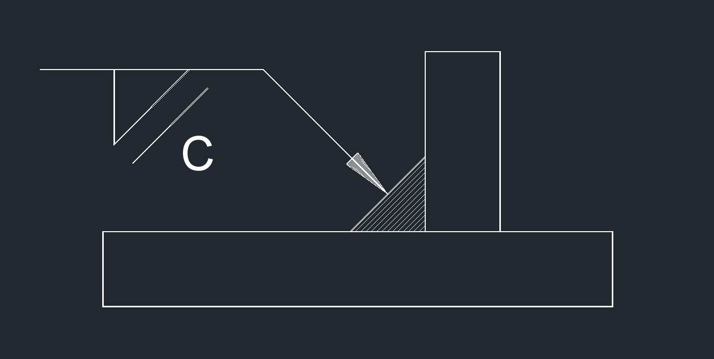 Miter Chipping Fillet
 Convex Contour Fillet
 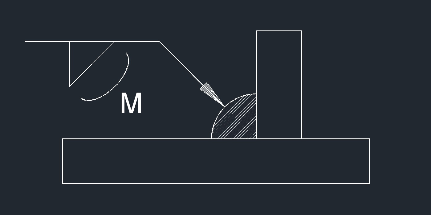 Convex Machining Fillet
 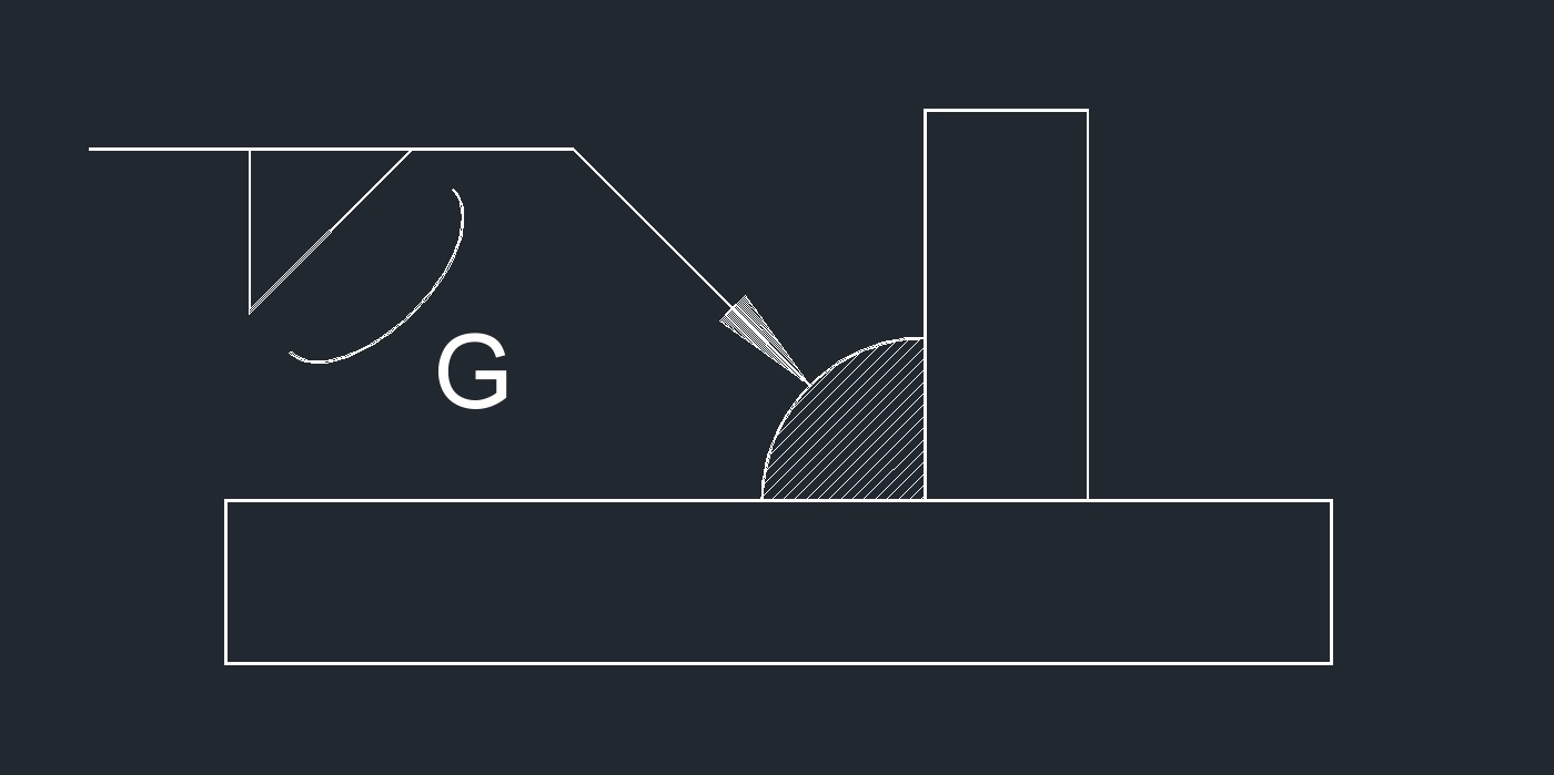 Convex Grinding Fillet
 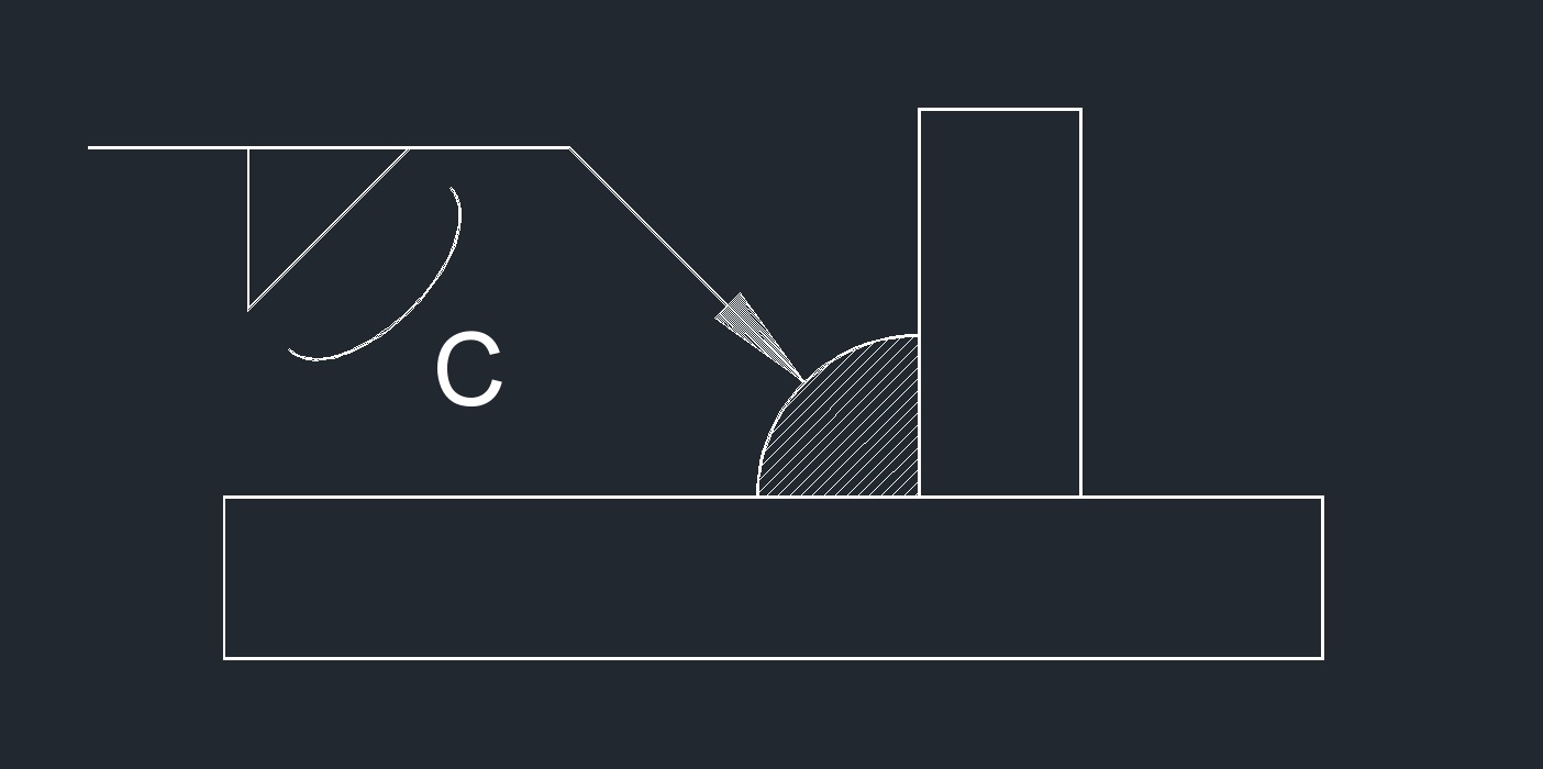 Convex Chipping Fillet
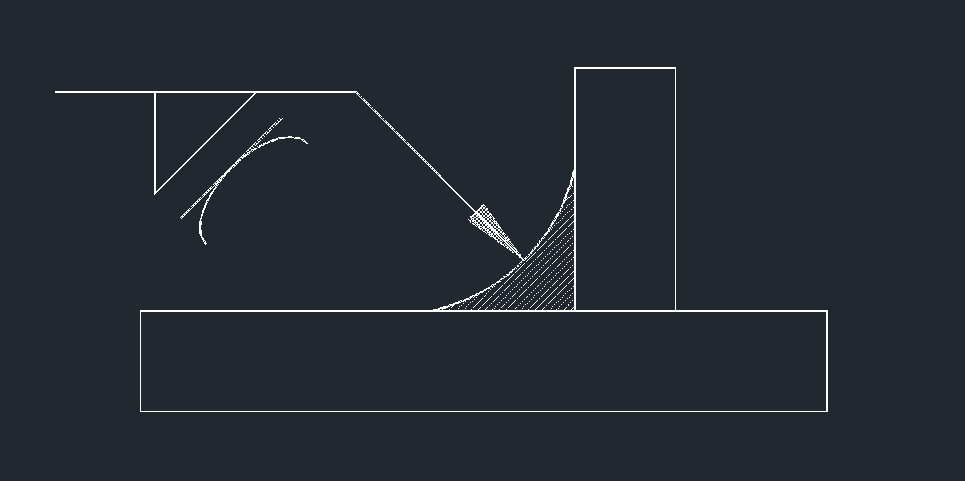 Concave Contour Fillet
 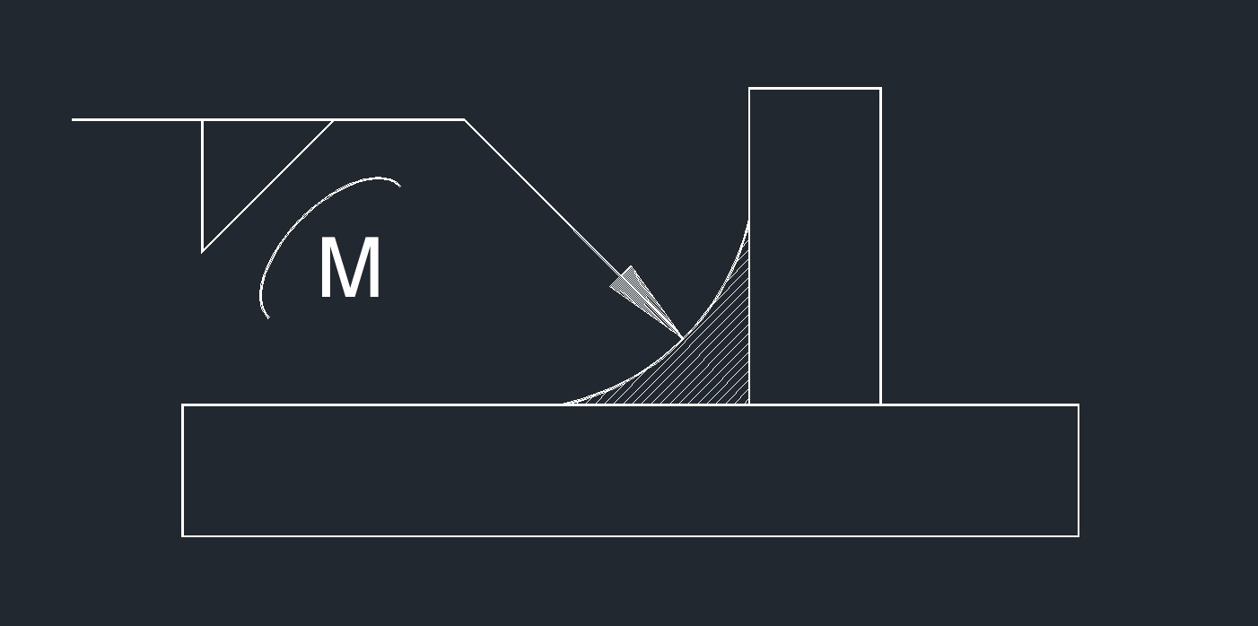 Concave Machining Fillet
 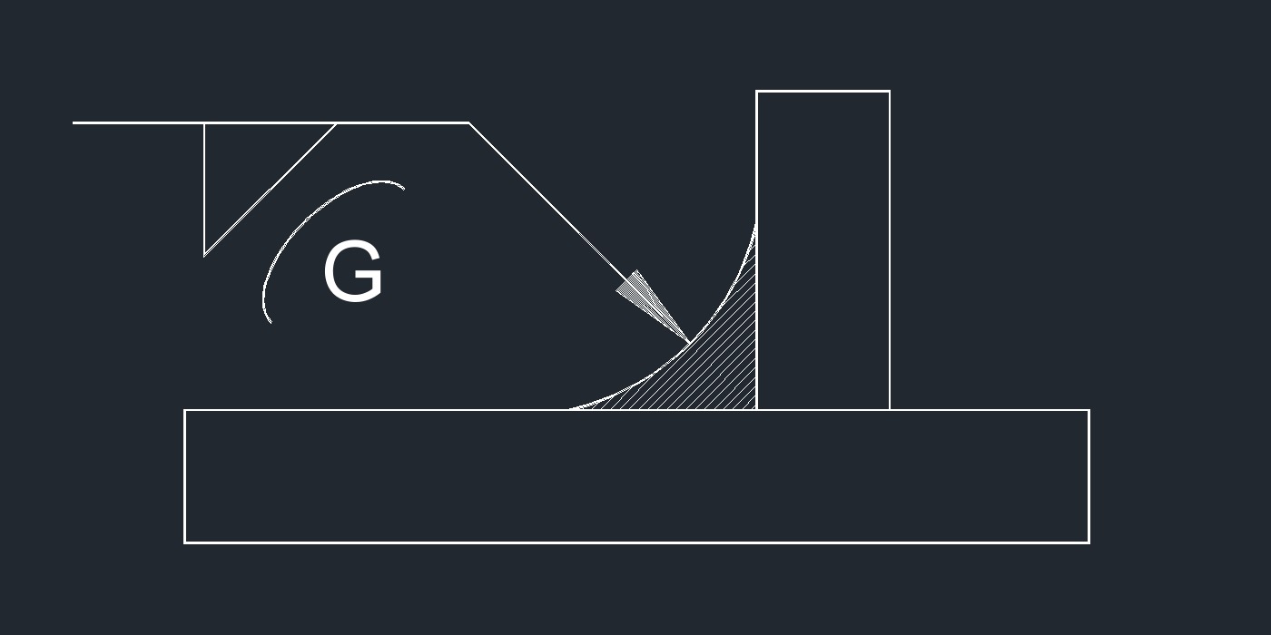 Concave Grinding Fillet
 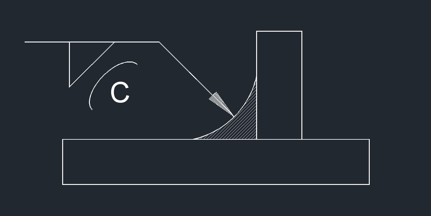 Concave Chipping Fillet