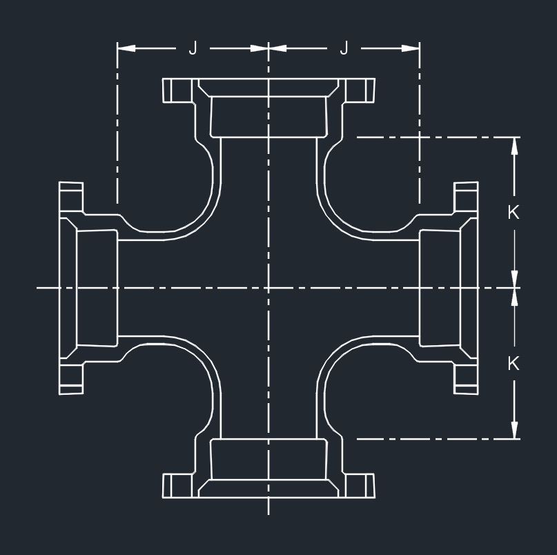
 MJ x MJ x MJ x MJ
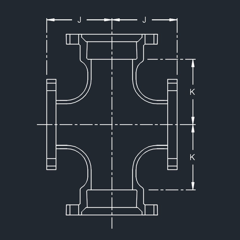 MJ x MJ x FLG x FLG
Mechanical Joint Crosses - Full Body, AWWA C110, DI (in)
| ||||||
|---|---|---|---|---|---|---|
| Pipe Size | Dimensions (in) | Approx. Weight (lb) | ||||
| Run | Branch | J | K | MJ | * MJ x FLG | |
| 6 | 6 | 8.0 | 8.0 | 160 | 141 | |
| 8 | 4 | 9.0 | 9.0 | 185 | - | |
| 8 | 6 | 9.0 | 9.0 | 205 | 182 | |
| 8 | 8 | 9.0 | 9.0 | 255 | 245 | |
| 10 | 6 | 11.0 | 10.0 | 285 | - | |
| 10 | 8 | 11.0 | 11.0 | 310 | - | |
| 10 | 10 | 11.0 | 11.0 | 380 | 360 | |
| 12 | 6 | 12.0 | 12.0 | 361 | 367 | |
| 12 | 8 | 12.0 | 12.0 | 371 | 373 | |
| 12 | 12 | 12.0 | 12.0 | 486 | 487 | |
| 14 | 8 | 14.0 | 14.0 | 550 | - | |
| 14 | 14 | 14.0 | 14.0 | 779 | - | |
| 16 | 6 | 15.0 | 15.0 | 650 | - | |
| 16 | 8 | 15.0 | 15.0 | 675 | 655 | |
| 16 | 16 | 15.0 | 15.0 | 895 | 875 | |
| 18 | 8 | 13.0 | 15.5 | 775 | - | |
| 18 | 10 | 13.0 | 15.5 | 760 | - | |
| 18 | 12 | 13.0 | 15.5 | 860 | - | |
| 18 | 18 | 16.5 | 16.5 | 1140 | - | |
| 20 | 8 | 14.0 | 17.0 | 951 | - | |
| 20 | 12 | 14.0 | 17.0 | 977 | - | |
| 20 | 16 | 18.0 | 18.0 | 1245 | - | |
| 20 | 20 | 18.0 | 18.0 | 1440 | - | |
| 24 | 8 | 15.0 | 19.0 | 1244 | - | |
| 24 | 12 | 15.0 | 19.0 | 1326 | - | |
| 24 | 16 | 15.0 | 19.0 | 1479 | - | |
| 24 | 20 | 22.0 | 22.0 | 1965 | - | |
| 24 | 24 | 22.0 | 22.0 | 2192 | - | |
| 30 | 6 | 18.0 | 23.0 | 2085 | - | |
| 30 | 12 | 18.0 | 23.0 | 2165 | - | |
| 30 | 24 | 25.0 | 25.0 | 3180 | - | |
| 30 | 30 | 25.0 | 25.0 | 3640 | - | |
| 36 | 24 | 20.0 | 26.0 | 2910 | - | |
| 36 | 36 | 28.0 | 28.0 | 4370 | - | |
| 42 | 42 | 31.0 | 31.0 | 7145 | - | |
| 48 | 24 | 26.0 | 34.0 | 5210 | - | |
| 48 | 36 | 34.0 | 34.0 | 6790 | - | |
| 48 | 48 | 34.0 | 34.0 | 9380 | - | |
![]()