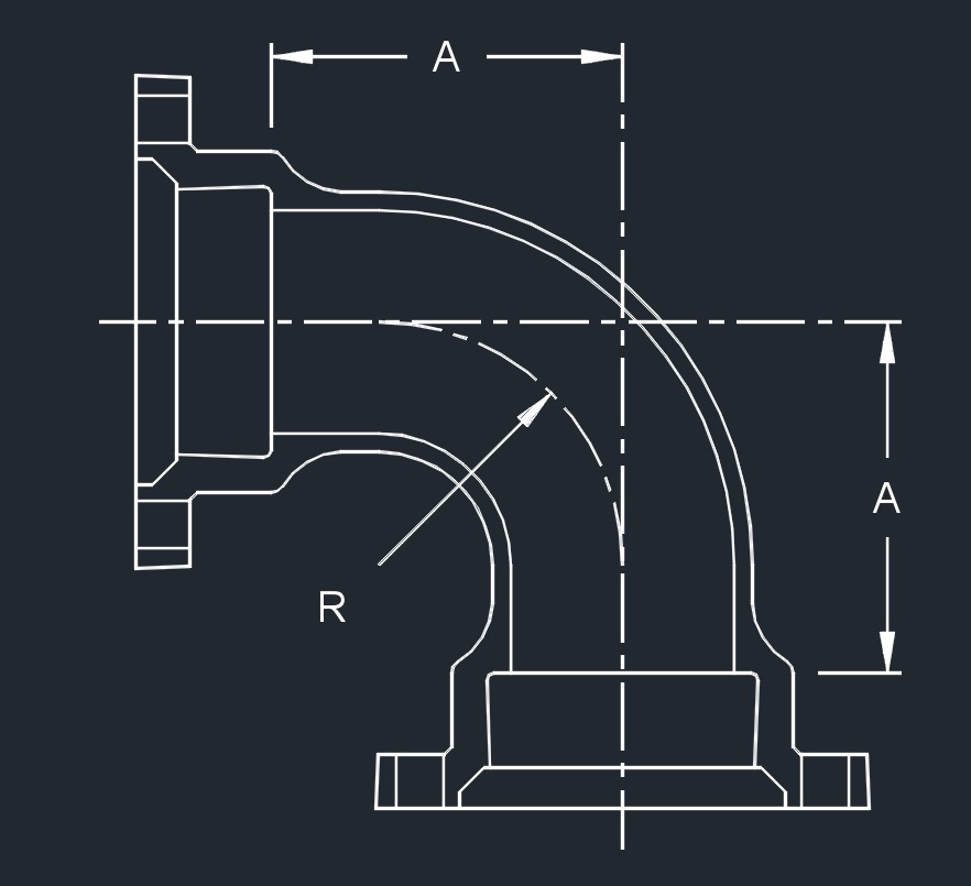
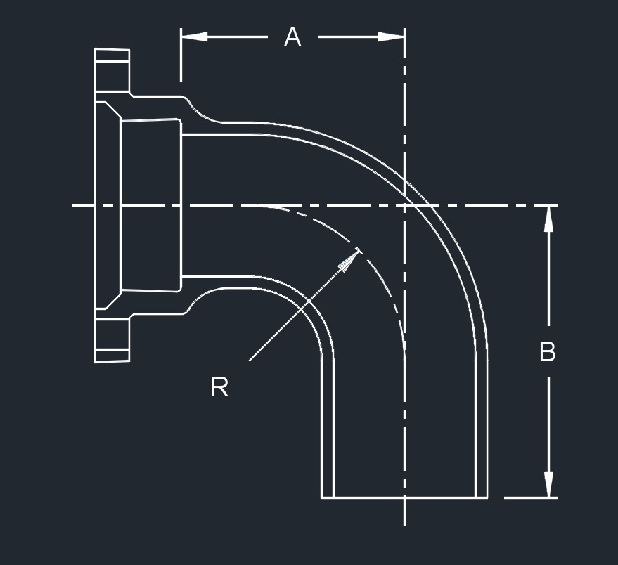
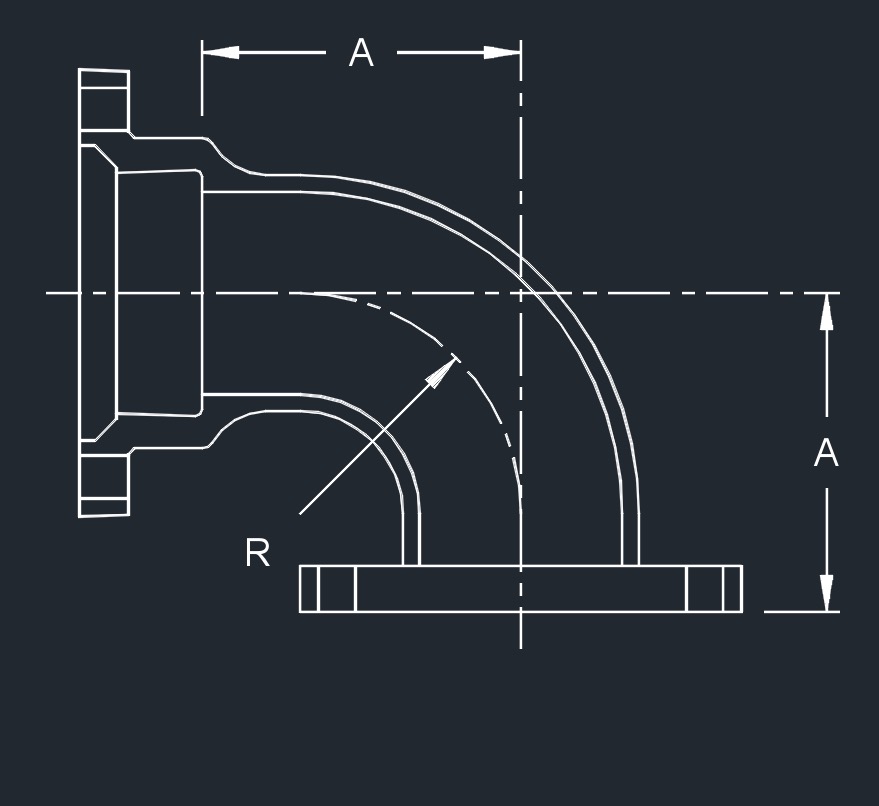
Mechanical Joint 90 Bends - Full Body, AWWA C110, DI (in)

on . Posted in Ductile Iron Flanged Fitting Datasheets


mj bend 90 1 diMJ x MJ

mj bend 90 3 diMJ x PE

mj bend 90 2 diMJ x FLG


Mechanical Joint 90 Bends - Full Body, AWWA C110, DI (in)

  • *  These fittings are not included in AWWA C110/A21.10
  • For flange dimensions see Flange - ANSI Class 125, C110, DI
  • AWWA C110/A21.10 - Ductile-Iron and Gray-Iron Fittings (3" to 48")
  • ASME B16.1 - Gray Iron Pipe Flanges and Flanged Fittings: Classes 25, 125, and 250 (Flange surfaces shall be faced and drilled in accordance with ANSI Class 125)
  • AWWA C104/A21.4 - Standard for Cement-Mortar Lining for Ductile-Iron Pipe and Fittings for Water
  • AWWA C111/A21.11 - Rubber-Gasket Joints for Ductile-Iron Pressure Pipe and Fittings
  • Ductile iron mechanical joint fittings 3" through 24" shall be rated for 350 PSI working pressure.
  • Flanged ductile iron fittings in 24 inch and smaller sizes may be rated for 350 psi with the use of special gaskets.
  • MJ - mechanical joint
  • PE - plain end
  • FLG - flange
Pipe SizeDimension (in)Approx. Weight (lb)
RABMJ x MJMJ x PEMJ x FLG
*  2 2.25 3.25 - 16 - -
3 4.0 5.5 13.5 26 36 -
4 4.5 6.5 14.5 56 53 51
6 6.0 8.0 16.0 88 80 75
8 7.0 9.0 17.0 123 119 118
10 9.0 11.0 19.0 189 181 168
12 10.0 12.0 20.0 268 252 288
14 11.5 14.0 22.0 380 - -
16 12.5 15.0 23.0 552 470 465
18 14.0 16.5 24.5 625 600 577
20 15.5 18.0 26.0 862 775 -
24 18.5 22.0 30.0 1423 1301 1150
30 21.5 25.0 33.0 1942 1920 -
36 24.5 28.0 36.0 2629 2310 -
42 27.5 31.0 - 3410 - -
48 30.5 34.0 - 4595 - -


 Piping Designer Logo 1