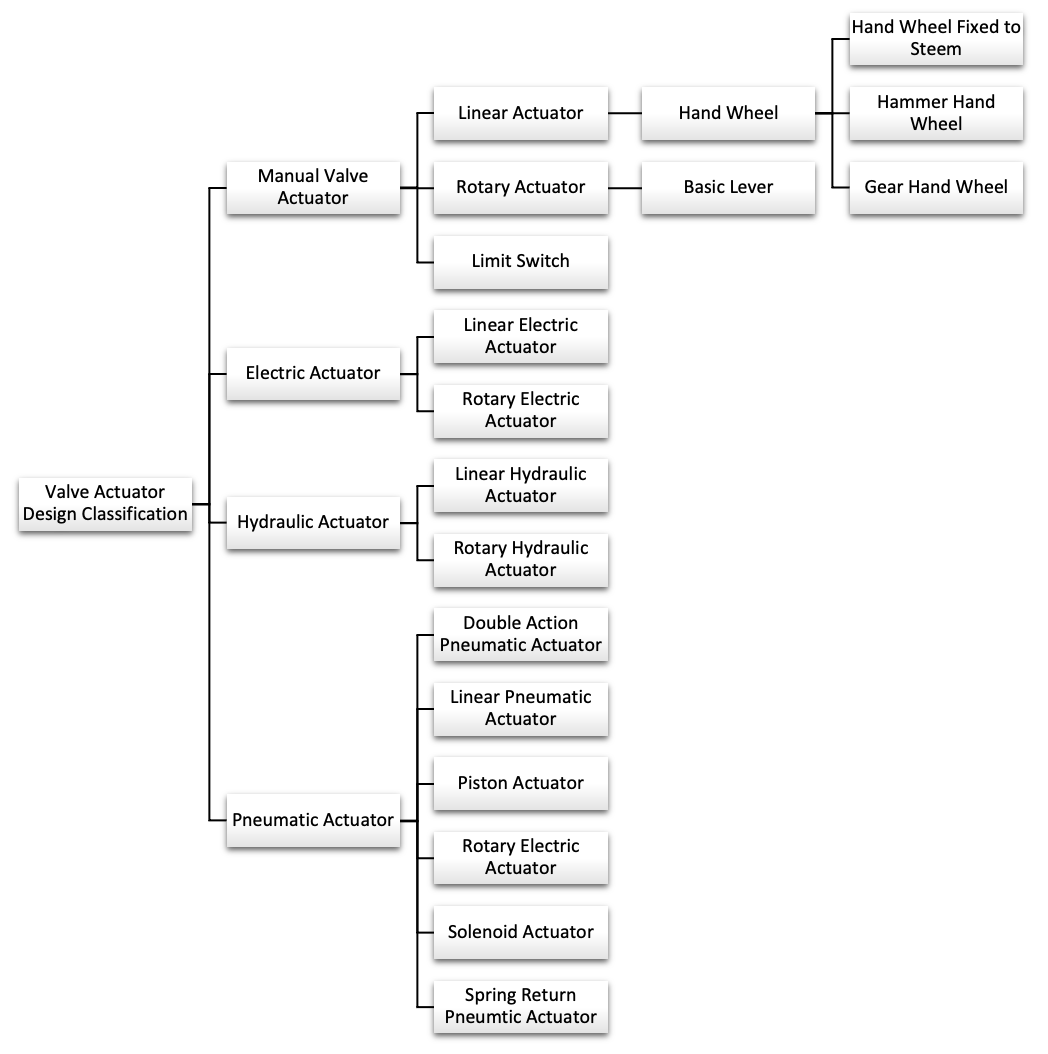
 Manual Valve Actuator - The actuator can shift a valve to the right position without using an external power source. Manual actuators use levers, wheels, and/or gears to facilitate movement. Manual actuators differ from automatic actuators, as automatic actuators have an external power source providing the force and motion needed to operate a valve automatically or remotely.
- Linear Actuator - Linear actuators differ in terms of valve stem stroke length, number of turns, and actuator force or seating thrust.
- Hand Wheel - Larger valves that require high torque to operate often use geared hand wheels. These operators have a large hand wheel with a gearbox that further increases the mechanical advantage. The radius of the wheel and gearing ratio determines the amount of mechanical advantage provided.
- Hand Wheel Fixed to Steem - The hand wheel fixed to the stem provides a mechanical advantage. In higher temperatures, these types of handwheels fixed are susceptible to thermal binding. When you shut of a valve while it is hot and allow it to cool, it can get stuck, making it impossible for you to reopen the valve.
- Hammer Hand Wheel - Comprises of a wheel, lug, and second wheel attached to a threaded stem. Based on the design, the primary wheel moves through a portion of its turn freely and then hits against the lug in the second wheel.
- Gear Hand Wheel - Depending on the design of the valve, you may need to fit in manually operated gears around the bonnet for additional mechanical help. This is especially useful for large valves that can only be operated by two people at the same time.
- Hand Wheel - Larger valves that require high torque to operate often use geared hand wheels. These operators have a large hand wheel with a gearbox that further increases the mechanical advantage. The radius of the wheel and gearing ratio determines the amount of mechanical advantage provided.
- Rotary Actuator - Rotary actuators vary in terms of actuator torque and range of motion. Depending on the valve’s design, the stem may rise during rotation or without rotation.
- Basic Lever - The most common manual operator on smaller quarter-turn valves. A long handle is attached to the stem and provides the leverage needed to rotate the valve.
- Limit Switch - Many times manual valves perform a function that does not require automated actuation, but the system still needs to know what postion they are in. Manual valves with limit switches or position indicators. While the valve is still operated manually, the switches communicate the valve's current position to the control system.
Electrical Actuator - Uses an alternating current or direct current motor to generate the torque required for valve operation. The motor is attached to the valve stem through a series of gears and controlled by a cam-activated limit switch. Together, these components allow for accurate and precise adjustment of the valve.
- Linear Electrical Actuator - This converts electricity into linear motion to operate a linear valve.
- Rotary Electrical Actuator - This converts electricity into rotary motion to operate a rotary valve.
Hydraulic Actuator - Hydraulic actuators are hydraulic devices that are propelled by pressured fluids like hydraulic fluid. The hydraulic actuated valves of the same size are typically more powerful than pneumatic actuators.
- Linear Hydraulic Actuator -
- Rotary Hydraulic Actuator - With a quarter turn or more from open to closure, rotary actuators are employed for valves with rotating motion like butterfly, ball, and plug valves. A disc or an ellipse that revolves around an angular shaft typically serves as the closing element.
Pneumatic Actuator (Hydraulic) - Pressurized air is utilized to turn a valve. They accomplish this by exerting air pressure (force) on a piston or a diaphragm that is fastened to the valve stem.
- Double Action Pneumatic Actuator - Require air to be used to move the piston in either direction. A solenoid valve is used to control the air flow into and venting of the actuator. Since there is no spring force to overcome, a smaller actuator can often be used.
- Linear Pneumatic Actuator - This convert the energy from compressed air into linear motion to operate linear valves.
- Piston Actuator - If the stroke of a diaphragm actuator is too low or the thrust is insufficient, piston actuators are employed. A solid piston inside a solid cylinder is subjected to compressed air. The reasonable designs urge the piston higher by pressing air into a central chamber.
- Rotary Electrical Actuator - This convert the energy from compressed air into rotational motion to operate rotary valves.
- Solenoid Actuator - A solenoid valve is an electrically controlled valve. The valve has a solenoid, which is an electric coil with a movable ferromagnetic core, or plunger, in its center. In the rest position, the plunger closes off a small orifice. An electric current through the coil creates a magnetic field. The magnetic field exerts an upwards force on the plunger opening the orifice. This is how it open and close valve.
- Spring Return Pneumatic Actuator - Use compressed air to move the piston in one direction, and a spring to push it back in the other when the air is stopped an allowed to vent. This requires a larger actuator since it has to overcome the force of the spring in addition to providing enough torque to operate the valve.
![]()