
Pipe Flange
 Flange, abbreviated as FLG, is a bolted connection where two pieces of pipe, equipment, fittings or valves are connected together to form a piping system. Flanges provide access for when equipment (or piping) needs to be cleaned, inspected or reconfigured. A flange pair is made up of two flanges and a gasket with bolts and nuts. Pipe flanges come in different styles, pressure ratings, materials and sizes to meet the design requirements. In the oil field, the two most commonly used flange standards are ANSI/ASME B16.5 and BS 1560. API Spec 6A is for flanges used on wellhead and christmas tree equipment.
Flanges of different standards or materials are not normally joined together. There are instances where the design may require dissimilar metals or different classifications are required to be bolted together. When this happens, be sure to seek engineering advise to ensure that the design is still within compliance with the applicable standards and specifications.
- Tags: Abbreviations Nomenclature and Symbols Pipe Pipe Fitting Pipe Flange Valve Gasket ASME Standards Pipeline Pipe Flange Datasheets Gasket Datasheets Pipe Spacing Datasheets
Pipe Flange Index
- Pipe Flange Design Classification
- Specialty Pipe Flange Design Classification
- Pipe Flange Datasheets
- Pipe Flange Standards
- Pipe Flange Classes
- Pipe Flange Facing
- General Pipe Flange Standards
- Pipe Flange Pressure Classes
- Pipe Flange Specification, BSI
- Pipe Flange Abbreviations
- Pipe Flange Glossary
Science Branches
|
| Science |
| Applied Science |
| Engineering |
| Mechanical Engineering |
|
Pipe Flange Design Classification
There are six basic types of flanges and are described by the way the connect to the piping system. Click on the links below to be taken to a page detailing the different types of flanges.
- Blind Flange - These flanges do not have a bore. It is used to blind off a flange or even a valve. When used at the end of a pipe or fitting, it provides an easy to open access for further extension of the pipe. The blind flange and its bolts are stressed more than any other flange.
- Lap Joint Flange - This flange is used with a lap joint stub end fitting. It is similar to a slip-on flange, but with two differences. The radius and the flat face, both allow the flange to secure against the stub end fitting. This is useful where alignment of bolt holes is difficult, such as with spools to be attached to flanged nozzles of vessels. A lap joint is used in low pressure applications and not suitable where high external of heavy loads are present.
- Slip-on Flange - Slip-on flanges are designed to slip over the outside of pipe, long-tangent elbows, reducers, and swages. The flange has poor resistance to shock and vibration. It is easier to align than a weld neck flange. This flange is ideal for low pressure applications since the strength when under internal pressure is about one third that of a weld neck flange.
- Socket Weld Flange - This is similar to a slip-on flange, except they have a bored and counter bore. The counter bore allows the pipe to fit into the socket/counter bore. The bore of the flange is the same diameter as the inside of the pipe. These flanges were first designed for small diameter, high pressure pipe.
- Threaded Flange - It is similar to a slip-on Flange, but has internal threads. It is normally used for low pressure and not used where temperature or stress is very high.
- Weld Neck Flange - This flange comes in two types, regular and long. The hub of the weld neck is designed to reduce the stress at the base of the flange. Regular weld neck flanges are used with buttweld fittings and long weld neck flanges are usually used with equipment and vessel nozzles. A long weld neck flange is rarely used with pipe. Both types of flanges are bored to match the inside diameter of the pipe or fitting to which it will be welded to. They are suitable where high pressure, extreme temperatures, shear impact and vibratory stresses apply.
Specialty Pipe Flange Design Classification
- Orifice Flange - Orifice flanges are for metering the volumetric flow rate of liquids and gasses through a pipe. This flange is normally available in weld neck, slip-on, and threaded flanges.
- Standard Connection Flange - This flange is normally used for nozzles on pressure vessels and rarely used with pipe.
- Expander Flange - An expander flange is similar to a weld neck flange but with the hub expanding to a larger size (one or two sizes).
- Reducing Flange - Reducing flanges are designed for when there is a change in the pipe size.
- Studding Outlet Flange: Flat Bottom Mount - Shell/Head Mount - Tangential Mount - These flanges have shaped welded ends to match a tank or vessel.
- Weldoflange / Nipoflange - A weldoflange is an olet connection, it is simular to a nipoflange, both are used for a branch connection on a pipe.
Pipe Flange Datasheets
| Pipe Flange Type | Datasheets |
|---|---|
| Flanges | All Flanges, ANSI (in) |
| Blind | Blind Flange, ANSI (in) |
| Ductile Iron | Ductile Iron Flange, ANSI (in) |
| Expander | Expander Flange, ANSI (in) |
| Flange Bolt | Flange Bolt, ANSI (in) |
| Lap Joint | Lap Joint Flange, ANSI (in) |
| Orifice | Orifice Flange, ANSI (in) |
| Slip-on | Slip-on Flange, ANSI (in) |
| Socket | Socket Flange, ANSI (in) |
| Standard Connection | Standard Connection Flange, ANSI (in) |
| Studded Outlet | Studded Outlet Flange, ANSI (in) |
| Threaded | Threaded Flange, ANSI (in) |
| Weld Neck | Weld Neck Flange, ANSI (in) |
Pipe Flange Standards
ASME Standards
- ASME B16.1 - Gray Iron Pipe Flanges and Flanged Fittings: Classes 25, 125, and 250
- ASME B16.5 - Pipe Flanges and Flanged Fittings: NPS 1/2 through NPS 24 Metric/Inch Standard
- ASME B16.20 - Ring Joint Gaskets and Grooves for Steel Pipe Flanges
- ASME B16.21 - Nonmetallic Flat Gaskets for Pipe Flanges
- ASME B16.24 - Cast Copper Alloy Pipe Flanges and Flanged Fittings: Classes 150, 300, 600, 900, 1500, and 2500
- ASME B16.34 - Large Diameter Steel Flanges (NPS 26 through NPS 60)
- ASME B16.36 - Orifice Flanges
- ASME B16.42 - Ductile Iron Pipe Flanges and Flanged Fittings: Classes 150 and 300
- ASME B16.47 - Large Diameter Steel Flanges (NPS 26 Through NPS 60)
ASTM Standards
- ASTM A105 - Specification for Carbon Steel Forgings for Piping Applications
- ASTM A182 - Specification for Forged or Rolled Alloy Steel Pipe Flanges, Forged Fittings, and Valves and Parts for High Temperature Service
- ASTM A193 - Specification for Alloy Steel and Stainless Steel Bolting Materials for High Temperature Service
- ASTM A194 - Specification for Carbon and Alloy Steel Nuts for Bolts for High Pressure and High Temperature Service
- ASTM A694 - Specification for Carbon and Alloy Steel Forgings for Pipe Flanges, Fittings, Valves, and Parts for High-Pressure Transmission Service
- ASTM A707 - Specification for Flanges, Forged, Carbon and Allow Steel for Low Temperature Service
AWWA Standards
- AWWA C115 - Standard for Flanged Ductile Iron Pipe with Ductile-Iron or Gray-Iron Threaded Flanges
ISO Standards
- ISO 5251 - Stainless steel butt-welding fittings
MSS Standards
- MSS SP-6 - Standard Finishes for Contact Faces Pipe Flanges and Connecting End Flanges of Valves and Fittings
- MSS SP-9 - Spot Facing for Bronze, Iron and Steel Flanges
- MSS SP-25 - Standard Marking Systems for Valves, Fittings, Flanges, and Unions
- MSS SP-44 - Steel Pipeline Flanges
- MSS SP-53 - Quality Standards for Steel Castings and Forgings for Valves, Flanges and Fittings and Other Piping Components - Magnetic Particle
- MSS SP-54 - Quality Standards for Steel Castings and for Valves, Flanges and Fittings and Other Piping Components - Radiographic
- MSS SP-55 - Quality Standards for Steel Castings and for Valves, Flanges and Fittings and Other Piping Components - Visual
- MSS SP-75 - High Test Wrought Butt Welding Fittings
- MSS SP-106 - Cast Copper Alloy Flanges and Flanged Fittings Class 125,150, and 300
- ASME B16.5 and ASME B16.47 cover pipe flanges up to NPS 60 (B16.5 from 1/2" to 24" and B16.47 from 26" to 60"). ANSI B16.47 covers two series of flanges, Series A is equal to MSS SP-44-44, and Series B is equal to API 605 (API 605 has been canclled).
Pipe Flange Classes
Only the most used flange classes are listed on this page. For more information on flanges and their respective standards, please follow the link below.
ASME B16.5 covers flanges with a nominal size from 1/2" through 24". It also includes classes from ANSI 150 through ANSI 2500. The flanges included in B16.5 are blind, lap joint, socket, slip-on, threaded and weld neck flanges.
ASME B16.47 covers flange with a nominal size of 24" and larger. The flange classes it covers are from ANSI 75 through ANSI 900. The flanges included are blind and weld neck flanges. Additionally, B16.47 has two series of flanges, Series A (similar to ASME MSS SP44) & Series B (similar to API 605). Series A flanges are larger, heavier and have fewer bolt holes. The reason for series A and series B is that both specifications mentioned before were brought together to be covered under ASME B16.47.
Pipe Flange Facing
There are three primary types of flange facings. Not all facings are available with each end connection. This is based on the design of the flange and design of the piping system. The typical flange facings are:
- Raised Face Flanges (RF)
- Flat Face Flanges (FF)
- Ring Type Joint Flanges (RTJ)
General Pipe Flange Standards
- Flange - ASME B16.36, Orifice Flange (1/2"-24")
- Slip-on Flange: Class 300, Class 400, Class 600, Class 900, Class 1500
- Threaded Flange: Class 300, Class 400, Class 600, Class 900, Class 1500
- Weld Neck Flange: Class 300, Class 400, Class 600, Class 900, Class 1500, Class 2500
- Flange - Industry Standard Flange (also called Large Diameter Flange) (26"-larger)
- Industry Standard Flanges have no national standard code or are they covered by any governing body.
- Blind Flange: Class 75, Class 125, Class 175, Class 250, Class 350
- Weld Neck Flange: Class 75, Class 125LW, Class 125, Class 175, Class 250, Class 350
- Slip-on Flange: Class 75, Class 125LW, Class 125, Class 175, Class 250, Class 350
- Industry Standard Flanges have no national standard code or are they covered by any governing body.
- Flange - AWWA Standard Flange
- AWWA C207
- Steel Ring Flange: Class B, Class D, Class E, Class F
- Steel Hub Flange: Class D, Class E
- Blind Flange: Class B, Class D, Class E, Class F
- AWWA C207
- Steel Ring Flange: Class B, Class D, Class E, Class F
- Steel Hub Flange: Class D, Class E
- Blind Flange: Class B, Class D, Class E, Class F
- AWWA C207
Pipe Flange Pressure Classes
Flanges are normally manufactured in seven basic ratings: 150 Lb, 300 Lb, 400 Lb, 600 Lb, 900 Lb, 1500 Lb and 2500 Lb. The ratings can be expressed in different ways but mean the same thing - 150 Lb, 150 Lbs, 150# or Class 150.
Each class of flange can handle more pressure than the previous class because of its construction. The higher the class is, the thicker the metal is. Thus a higher pressure can be handled. There a numerous factors that can affect the pressure capability of a flange, such as the type of metal that is used.
Pipe Flange Specification, BSI
The BSI specifications for flanges are:
- BS 10 - Specification for Flanges and Bolting for Pipes, Valves, and Fittings
- BS 3293 - Specification for Carbon Steel Pipe Flanges (over 24 inches nominal size) for the Petroleum Industry
- BS 4504 - Specification for Steel Flanges Circular Flanges for Pipes, Valves and Fittings
- ISO 7005-1 - Metallic Flanges - Part 1: Steel Flanges (this is substantially the same as BS 4504)
BSI Flange Materials
Standards usually specify the material from which the flange is produced.
BSI Flange Sizes
There are available flange sizes and grades for all standard pipe wall thicknesses and pressure ratings.
BSI Flange Facing Types
The typical flange faces used are flat face, raised face, tongue and groove and ring joint.
BSI Flange Finish
The flange face finish is determined by the standard used and measured as an Arithmetical Average Roughness Height (AARH). An example would be ANSI B16.5 which specifies face finishes within a range 125AARH - 500AARH (3.2 Ra to 12.5 Ra).
BSI Flange Class Rating | ||
|---|---|---|
| Flange
Type | BS4504
(ISO 7005-1) DN 10 to DN 4000 | BS2393
26"-60" |
| Blind | 2.5-40 | - |
| Lap Joint | 6-40 | - |
| Slip-On | 2.5-40 | 150-600 |
| Socket | - | - |
| Threaded | 6-40 | - |
| Weld Neck | 2.5-40 | 150-600 |
| Flat/Raised Facing | As Above | As Above |
| Ring Joint Facing | 2.5-40 | 300-600 |
| Other Facings | 2.5-40 | - |
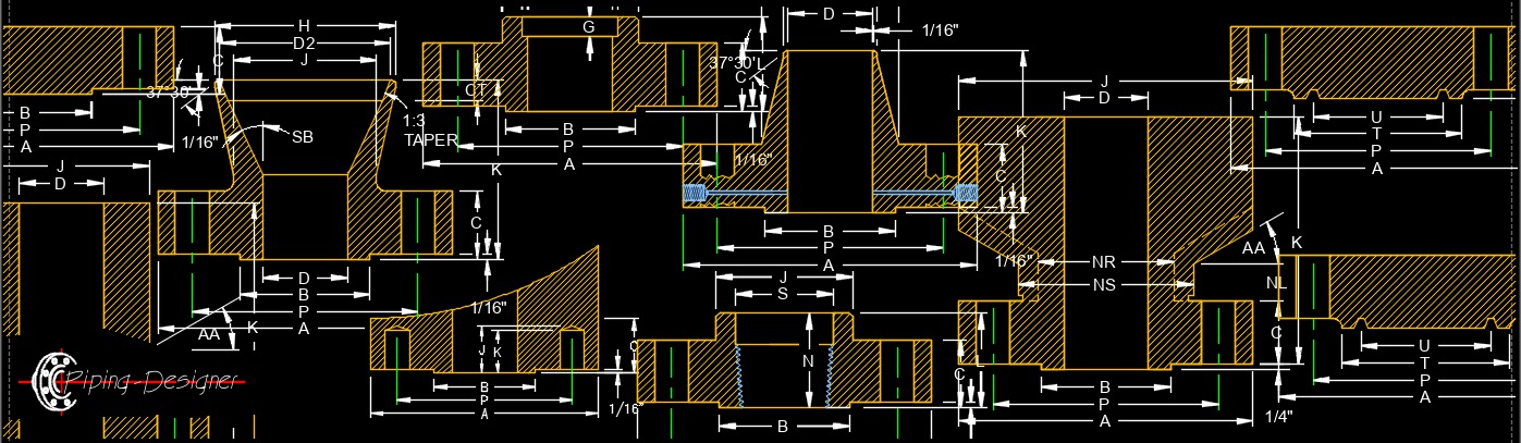
Pipe Flange Abbreviations |
||
|
|
|
Pipe Flange Glossary
A
- A - B - C - D - E - F - G - H - I - J - K - L - M - N - O - P - Q - R - S - T - U - V - W - X - Y - Z
B
- A - B - C - D - E - F - G - H - I - J - K - L - M - N - O - P - Q - R - S - T - U - V - W - X - Y - Z
- Blind Flange - A piping component for covering or closing the end of a pipe, valve, vessel or tank.
- Blowout - Occures when internal pressure tends to push the gasket material out from between flanges.
- Bolt Fracture - A type of fastener failure that occures when a fastener is over-tightened and causes the bolt to break.
- Bolt Hole Distortion - The flange is permanently distorted directly beneath the bolt. Caused by initial bolt torque.
- Bolt Load - The load generated by a bolt when it is tightened.
- Bolt Tightening Procedure - When tightening, always use the correct sequential bolt order for the flange.
- Bolt Torque - A rotational moment. It is a measure of how much twisting is applied to tighten (turn) the nut on a bolt.
- Breakaway Torque - The torque necessary to put into reverse rotation a bolt that has not been tightened.
C
- A - B - C - D - E - F - G - H - I - J - K - L - M - N - O - P - Q - R - S - T - U - V - W - X - Y - Z
- Cocking - When the flange of a mechanical assembly is not parallel to each other.
- Corrosion - The thinning of a pipe wall that is typically caused by a chemical reaction from a corroding fluid or agent and is limited almost exclusively to metal products.
D
E
F
- A - B - C - D - E - F - G - H - I - J - K - L - M - N - O - P - Q - R - S - T - U - V - W - X - Y - Z
- Facing - The contact surface finish of a flange.
- Fitting - A piping component that is used to join piping, change the direction or diameter of piping or end the pipe.
- Flange Bolt Circle - A flange is the theoretical circle on which the centerpoints of bolt holes lie when the bolt holes are positioned as equally spaced on the flange face.
- Flange Bolting Examples -
- Flange Dimension Tolerances, ASME B16.5 (in) -
- Flange Facings, ASME B16.5 - ASME B16.5 requires that for flanges and flanged fittings the surface is to have a specific roughness.
- Flange Pressure and Temperature Ratings, B16.5 - The following table is the maximum allowable non-shock pressure and temperature ratings for various flanges.
- Flange Specification, BSI -
- Flange Stamping - All flanges should be stamped for identification on the outside diameter of the base for easy identification.
- Flange Welding Bevel Standard, ANSI B16.5 and B16.47 - This article outlines the requirements for the beveling of flanges to be in compliance with ANSI/ ASME B16.56 and B16.47.
- Flat Faced Flange - A flange that is machined flat and does not have a ridge like a raised face or ring type joint flange.
G
- A - B - C - D - E - F - G - H - I - J - K - L - M - N - O - P - Q - R - S - T - U - V - W - X - Y - Z
- Gasket - A seal between two components, usually bolted.
- General Flange Standards -
H
I
J
K
L
- A - B - C - D - E - F - G - H - I - J - K - L - M - N - O - P - Q - R - S - T - U - V - W - X - Y - Z
- Lap Joint Flange - A flange that consists of two parts, a stub end and the backing flange.
- Leakage - The amount of fluid that will pass through a control valve when it is fully closed at a given pressure and temperature.
N
O
- A - B - C - D - E - F - G - H - I - J - K - L - M - N - O - P - Q - R - S - T - U - V - W - X - Y - Z
- Orifice Flange - For metering the volumetric flow rate of liquids and gasses through a pipe.
- Orifice Plate - Measures the flow of a liquid or gas by the difference in pressure from the upstream to the downstream.
- Orifice Plate Beta Ratio - The relative size of the orifice opening compared to the pipe diameter in which it is installed.
P
- A - B - C - D - E - F - G - H - I - J - K - L - M - N - O - P - Q - R - S - T - U - V - W - X - Y - Z
- Pipe - A hollow tube that can carry products such as fluid, gas, granular and more.
- Pipe End - There are three main types of pipe ends: beveled, threaded or plain.
- Pipe Schedule - The term used to describe the thickness of a pipe.
- Pipe Tap - Uses a cutting tool to create internal threads in a hole or pipe. It is specifically designed to create threads that conform to standard pipe thread sizes and specifications.
- Pressure - It is the force exerted perpendicular to the surface of an object and is expressed as force per unit area.
Q
R
- A - B - C - D - E - F - G - H - I - J - K - L - M - N - O - P - Q - R - S - T - U - V - W - X - Y - Z
- Raised Face Flange - The most common type of flange facing is the raised face flange. It is used in almost all applications in high and low pressures and temperatures.
- Raised Face Smooth Finish - More than several years ago, the standard finish on raised face flanges was around 500 microinch roughness.
- Reducing Flange - Designed for when there is a change in the pipe size.
- Ring Type Joint fFange - A type of flange that uses a metal ring that sits in a hexagonal groove as a gasket to seal the flange pair.
S
- A - B - C - D - E - F - G - H - I - J - K - L - M - N - O - P - Q - R - S - T - U - V - W - X - Y - Z
- Sealing Stress - The amount of flange pressure in a flanged joint assembly to compress and seat a gasket material in order to create an effective seal.
- Slip-on Flange - Designed to slip over the outside of pipe, long-tangent elbows, reducers, and swages.
- Socket Weld Flange - The socket weld flange, abbreviated as SWF, is similar to a slip-on flange, except only one fillet weld is made to the flange and pipe.
- Spec Blind - See Spectacle Blind
- Spectacle Blind - A safety device used to isolate a section of line or piece of equipment when the line or equipment needs to be inspected or removed from service.
- Standard Connection Flange - This flange is normally used for nozzles on pressure vessels and rarely used with pipe.
T
- A - B - C - D - E - F - G - H - I - J - K - L - M - N - O - P - Q - R - S - T - U - V - W - X - Y - Z
- Torque - The rotational force used to move a shart.
U
V
W
- Weld Neck Flange - A flange type that is usually used with pipes, as opposed to pressure vessels.
- Welding to a Flange - When welding a flange, fitting or a piece of pipe together the gap spacing for welding them is established by the Welding Qualification.
X
Y
Z
![]()
Tags: Pipe Pipe Fitting Pipe Flange Valve Gasket ASME Standards Pipeline Pipe Flange Datasheets Gasket Datasheets Pipe Spacing Datasheets