Allowable Pipe Span
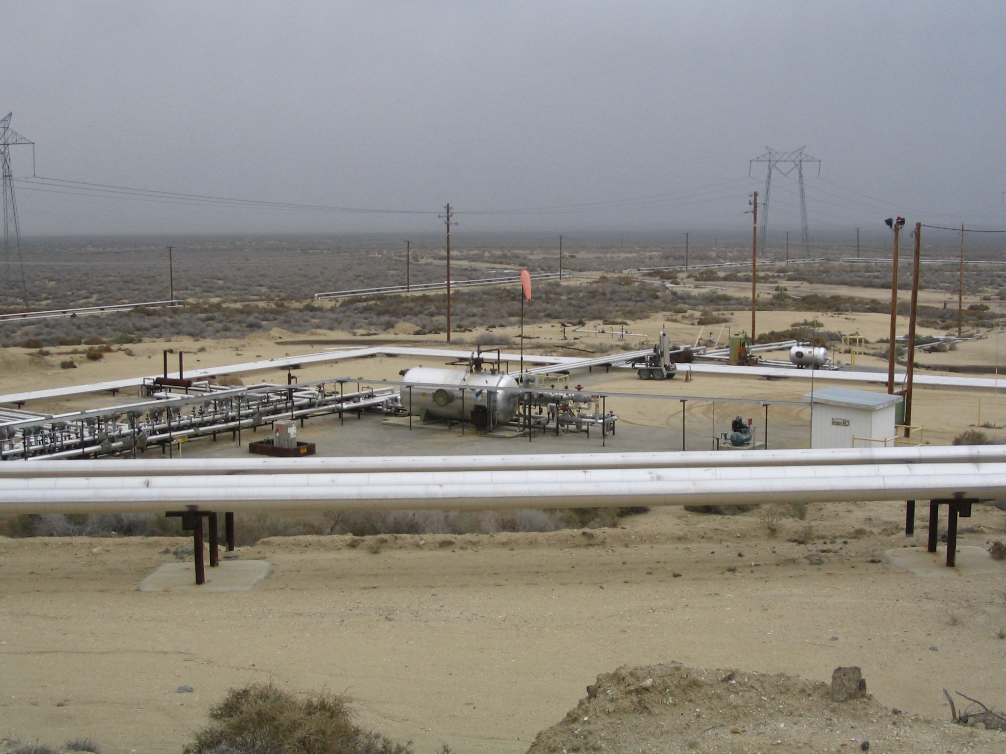
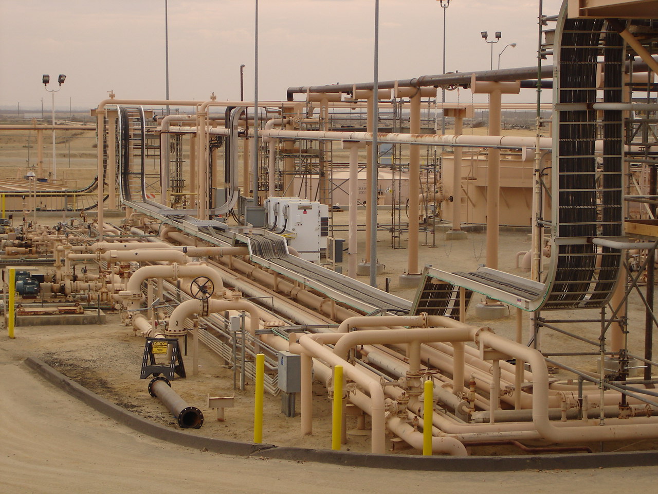
 Allowable pipe span is the maximum distance between supports or hangers that a pipe can span without excessive deflection or stress. It's an important parameter in piping design and engineering to ensure the structural integrity and safety of a piping system. Properly supported pipes help prevent sagging, vibrations, stress concentrations, and potential failures.
Supports Must be Placed with These Considerations
- The ability to place a support at some desired location.
- Keeping sag in the line within limits that will permit drainage.
- Avoid excess bending stresses from the uniform and concentrated loads between the supports.
General Steps and Considerations for Determining Allowable Pipe Spans
Determine Pipe Material and Size - Identify the material and size of the pipe. Different materials have different mechanical properties that influence their ability to span distances without additional support.
Pipe Diameter and Wall Thickness - Larger pipes with thicker walls are generally stiffer and can span longer distances without excessive deflection.
Consider Pipe Operating Conditions - Take into account the temperature of the fluid inside the pipe. High temperatures can affect the pipe's flexibility and thermal expansion.
Operating Pressure - Higher pressure pipes may need shorter spans to prevent deflection and stress.
Pipe Schedule - The schedule (wall thickness) of the pipe also affects its stiffness and deflection characteristics.
Refer to Applicable Codes and Standards - Various engineering codes and standards, such as ASME B31.1 for power piping or ASME B31.3 for process piping, provide guidelines for pipe support spacing. These codes are often specific to the industry and application.
Calculate Maximum Allowable Span - Use the relevant formulas or charts from the applicable code to calculate the maximum allowable span. These formulas may involve factors such as the modulus of elasticity, moment of inertia, and other mechanical properties of the pipe material.
Consider Support Types - The type of supports used (e.g., hangers, trapeze supports, or spring supports) can impact the allowable span. The flexibility of the supports and their ability to accommodate thermal expansion should be taken into account.
Check for Additional Loadings - Consider other loads that the pipe may be subjected to, such as insulation, wind, seismic, or dynamic loads. These loads can affect the overall design and spacing of supports.
Allowable pipe span is typically calculated based on engineering principles and standards, taking into consideration deflection limits, stress limits, and dynamic factors like fluid flow induced vibrations. If a pipe span exceeds the allowable limits, it can lead to problems such as sagging, excessive stress, vibration, and reduced operational efficiency. It can also contribute to issues like leaks, fatigue, and potential pipe failures.
Piping designers and engineers use various methods and software tools to calculate allowable pipe spans based on the factors mentioned above. Ensuring proper support spacing is essential for maintaining the long term integrity and functionality of a piping system in various industries, including oil and gas, petrochemicals, water distribution, and more.
Allowable Pipe Span Dataseet
|
||||||
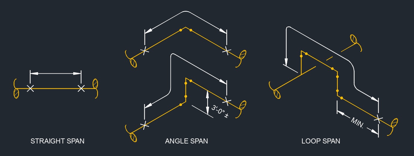
| Pipe Size (NPS) | Pipe Schedule | Wall Thickness | Straight Span | Angle Span | Loop Span | |
| Allowable Span | Deflection | |||||
| 3/4 | 80 | .154 | 10'-0" | 0.14" | 6'-0" | 8'-0" |
| 1 | 80 | .179 | 13'-0" | 0.36" | 7'-0" | 10'-0" |
| 1 1/2 | 80 | .200 | 17'-0" | 0.36" | 11'-0" | 13'-0" |
| 2 | 40 | .154 | 19'-0" | 0.39" | 12'-0" | 14'-0" |
| 2 | 80 | .218 | 20'-0" | 0.39" | 13'-0" | 15'-0" |
| 3 | 40 | .216 | 25'-0" | 0.53" | 16'-0" | 18'-0" |
| 4 | 40 | .237 | 27'-0" | 0.46" | 18'-0" | 20'-0" |
| 6 | 40 | .280 | 33'-0" | 0.50" | 22'-0" | 25'-0" |
| 8 | 30 | .277 | 36'-0" | 0.44" | 24'-0" | 27'-0" |
| 10 | 20 | .250 | 38'-0" | 0.45" | 25'-0" | 29'-0" |
| 10 | 40 | .365 | 41'-0" | 0.50" | 27'-0" | 31'-0" |
| 12 | 20 | .250 | 40'-0" | 0.43" | 26'-0" | 30'-0" |
| 12 | STD | .375 | 44'-0" | 0.51" | 29'-0" | 33'-0" |
| 14 | 10 | .250 | 42'-0" | 0.46" | 27'-0" | 31'-0" |
| 14 | STD | .375 | 46'-0" | 0.52" | 30'-0" | 34'-0" |
| 16 | 10 | .250 | 44'-0" | 0.74" | 28'-0" | 33'-0" |
| 16 | STD | .375 | 48'-0" | 0.50" | 31'-0" | 36'-0" |
| 18 | 10 | .250 | 45'-0" | 0.43" | 29'-0" | 34'-0" |
| 18 | STD | .375 | 50'-0" | 0.50" | 33'-0" | 38'-0" |
| 20 | 10 | .250 | 47'-0" | 0.45" | 31'-0" | 36'-0" |
| 20 | 20 | .375 | 52'-0" | 0.50" | 34'-0" | 39'-0" |
| 24 | 10 | .250 | 49'-0" | 0.42" | 32'-0" | 37'-0" |
| 24 | 20 | .375 | 55'-0" | 0.50" | 36'-0" | 41'-0" |


