Voltage Drop
Voltage Drop for Single-phase formula |
||
|
\( VD \;=\; \dfrac{ 2 \cdot Z \cdot I \cdot L }{ 1000 }\) (Voltage Drop for Single-phase) \( Z \;=\; \dfrac{ 1000 \cdot VD }{ 2 \cdot I \cdot L }\) \( I \;=\; \dfrac{ 1000 \cdot VD }{ 2 \cdot Z \cdot L }\) \( L \;=\; \dfrac{ 1000 \cdot VD }{ 2 \cdot Z \cdot I }\) |
||
| Symbol | English | Metric |
| \( VD \) = Voltage Drop | \(V\) | \(V\) |
| \( Z \) = Impedance of the Conductor (ohms per 1,000 ft) | \(\Omega\) | \(\Omega\) |
| \( I \) = Electric Current Load | \(A\) | \(A\) |
| \( L \) = Length of Conductor from Source to Load (One-way) | \(ft\) | \(m\) |

Voltage drop, abbreviated as \(VD\), is the electricity between the meter and where it is to be used. It is basically impossible to have no voltage loss. Voltage drop is the decrease in voltage along a conductor or a circuit element as current flows through it. It is a result of the resistance of the conductor or the circuit element, which causes energy to be dissipated in the form of heat.
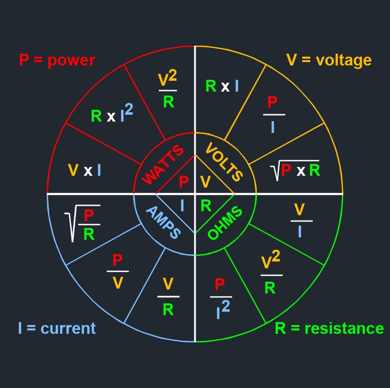
When current flows through a conductor or a component with resistance, such as a resistor, wire, or electrical device, there is a loss of voltage across that element. This loss is due to the resistance converting some of the electrical energy into heat. According to Ohm's Law, the voltage drop across a resistor or conductor can be calculated using the equation V = I * R.
Voltage Drop for Three-phase formula |
||
|
\( VD = \dfrac{ 1.732 \cdot Z \cdot I \cdot L }{ 1000 }\) (Voltage Drop for Three-phase) \( Z = \dfrac{ 1000 \cdot VD }{ 1.732 \cdot I \cdot L }\) \( I = \dfrac{ 1000 \cdot VD }{ 1.732 \cdot Z \cdot L }\) \( L = \dfrac{ 1000 \cdot VD }{ 1.732 \cdot Z \cdot I }\) |
||
| Symbol | English | Metric |
| \( VD \) = Voltage Drop | \(V\) | \(V\) |
| \( Z \) = Impedance of the Conductor (ohms per 1,000 ft) | \(\Omega\) | \(\Omega\) |
| \( I \) = Electric Current Load | \(A\) | \(A\) |
| \( L \) = Length of Conductor from Source to Load (One-way) | \(ft\) | \(m\) |
Voltage drop can occur in various parts of an electrical circuit, including the wiring, connectors, switches, and other components. Excessive voltage drop can lead to undesirable consequences, such as reduced efficiency, diminished performance of devices, and inadequate power delivery. In applications with sensitive electronics or where precise voltage levels are required, managing and minimizing voltage drop becomes critical.
To mitigate voltage drop, engineers and electricians often consider factors such as conductor size, wire length, resistance of components, and the allowable voltage drop limits for specific applications. By selecting appropriate wire gauges, reducing the length of the wire run, or employing voltage regulation techniques, they can minimize voltage drop and ensure that the intended voltage is maintained across critical components. Voltage drop calculations are important in electrical system design, power distribution, and load analysis. They help in assessing the performance and efficiency of electrical circuits and ensuring that the voltage supplied to devices or loads remains within acceptable limits.

