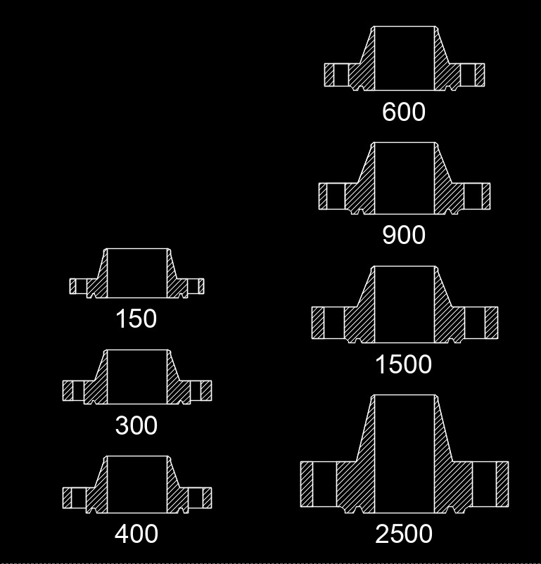
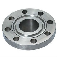
Ring Type Joint Flange
Ring type joint flange, abbreviated as RTJF, is a type of flange that uses a metal ring that sits in a hexagonal groove as a gasket to seal the flange pair. The flanges seal when the bolts are tightened and the gasket is compressed into the groove making a metal to metal seal. An RTJ flange usually has a raised face with the groove machined into the face of the flange. The raised face doesn’t serve as a way to contain the pressure.

 RTJ Flanges are used for high pressure applications up to pressures as high as 15,000 psi (103 MPa). It is only furnished only on steel or alloy valve bodies and usually need to specified when ordering. The flanges usually come in blind, slip-on, threaded and weld neck.
The benefits of using an RTJ flange and ring is that the gasket is confined to a groove and has two sealing surfaces. The groove assures that the ring centers itself when the bolts are tightened. It also is self actuating meaning that the sealing pressure increases when the process pressure increases.
The disadvantages of using RTJ flanges is that ring type joint grooves can accumulate dirt or moisture when the flange is open. Since the seal is a metal on metal connection, a small amount of damage on the narrow sealing surface(s) may lead to a leak. Additionally, the grooves and ring gasket must align properly in order to assemble the flange and obtain a seal. They must stay aligned throughout the operating cycle. This is important if you are flanging up to dissimilar metals like stainless steel to carbon steel flanges.
Ring Type Joint Flange Design Considerations
When removing the RTJ connection, the flanges must be forcibly separated to release the ring from the groove. Because of this, there needs to be sufficient access for removal of the flanges and removal of the ring.
With the wide acceptance of and significant usage of the spiral wound gasket in high pressure service, RTJ type flanges aren’t as common as raised face flanges. Consideration should be made during the design to ensure that additional rings are available when connections need to be broken.
Ring Type Joint Gasket Datasheets

