- See Article - Beam Design Formulas
Beam Fixed at Both Ends - Concentrated Load at Any Point formulas |
||
|
\( R_1 = V_1 \; (max.\; when \; a < b ) \;=\; \dfrac{ P\cdot b^2 }{ L^3 } \cdot ( 3 \cdot a + b ) \) \( R_2 = V_2 \; (max.\; when \; a > b ) \;=\; \dfrac{ P \cdot a^2 }{ L^3 } \cdot ( a + 3 \cdot b ) \) \( M_1 \; (max.\; when \; a < b ) \;=\; \dfrac{ P\cdot a\cdot b^2}{L^2 }\) \( M_2 \; (max. \;when \; a > b ) \;=\; \dfrac{ P\cdot a^2\cdot b }{ L^2 }\) \( M_a \; (at \;point \;of \;load ) \;=\; \dfrac{ 2\cdot P\cdot a^2\cdot b^2 }{ L^3 }\) \( M_x \; ( x < a ) \;=\; (R_1 \cdot x) - \dfrac{ P\cdot a\cdot b^2 }{ L^2 } \) \( \Delta_{max} \; (at \; x = \frac{2\;a\;L}{3\;a \;+\; b} \;when \;a > b ) \;=\; \dfrac{ 4\cdot P\cdot a^3\cdot b^2 }{ 3 \cdot \lambda \cdot I \cdot ( 3\cdot a + b )^2 } \) \( M_a \; (at \;point \;of \;load ) \;=\; \dfrac{ 2 \cdot P\cdot a^3\cdot b^3 }{ 6\cdot \lambda\cdot I \cdot L^3 }\) \( \Delta_x \; ( x < a ) \;=\; \dfrac{ 2 \cdot P\cdot b^2\cdot x^2 }{ 12\cdot \lambda \cdot I \cdot L^3 } \cdot ( 3\cdot a\cdot L - 3\cdot a\cdot x - b\cdot x ) \) \( x \; ( point\; of\; contraflexure\;between\;supports ) \;=\; \dfrac{ a\cdot b^2\cdot P }{ L^2\cdot R_1 }\) |
||
| Symbol | English | Metric |
| \( \Delta \) = Deflection or Deformation | \(in\) | \(mm\) |
| \( x \) = Horizontal Distance from Reaction to Point on Beam | \(in\) | \(mm\) |
| \( M \) = Maximum Bending Moment | \(lbf-in\) | \(N-mm\) |
| \( V \) = Maximum Shear Force | \(lbf\) | \(N\) |
| \( \lambda \) (Greek symbol lambda) = Modulus of Elasticity | \(lbf\;/\;in^2\) | \(Pa\) |
| \( I \) = Moment of Inertia | \(in^4\) | \(mm^4\) |
| \( R \) = Reaction Load at Bearing Point | \(lbf\) | \(N\) |
| \( L \) = Span Length Under Consideration | \(in\) | \(mm\) |
| \( a, b \) = Span Length Under Consideration | \(in\) | \(mm\) |
| \( P \) = Total Concentrated Load | \(lbf\) | \(N\) |
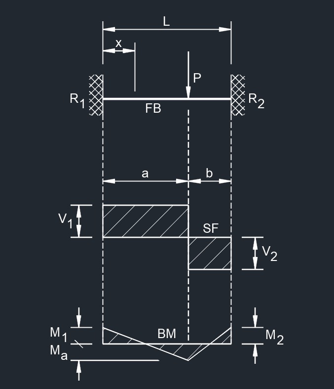
Diagram Symbols
Bending moment diagram (BMD) - Used to determine the bending moment at a given point of a structural element. The diagram can help determine the type, size, and material of a member in a structure so that a given set of loads can be supported without structural failure.
Free body diagram (FBD) - Used to visualize the applied forces, moments, and resulting reactions on a structure in a given condition.
Shear force diagram (SFD) - Used to determine the shear force at a given point of a structural element. The diagram can help determine the type, size, and material of a member in a structure so that a given set of loads can be supported without structural failure.
Uniformly distributed load (UDL) - A load that is distributed evenly across the entire length of the support area.
![]()