- See Article - Frame Design Formulas
Two Member Frame - Fixed/Fixed Top Point Load Formulas |
||
|
\( e \;=\; \dfrac{h}{L} \) \( \beta \;=\; \dfrac{ I_h }{ I_v } \) \( R_A \;=\; \dfrac{P\cdot x^2}{2\cdot L^3 \cdot \left( \beta \cdot e + 1 \right) } \cdot \left(\; \beta \cdot e \cdot \left( 3 \cdot L - x \right) + 2 \;\left( 3 \cdot L - 2 \cdot x \right) \;\right) \) \( R_D \;=\; P - R_A \) \( H_A = H_D \;=\; \dfrac{ 3 \cdot P \cdot x^2 }{ 2 \cdot h \cdot L^2 } \cdot \dfrac{ L - x }{ \beta \cdot e + 1 } \) \( M_A \;=\; \dfrac{ P \cdot x^2 }{ 2\cdot L^2 } \cdot \dfrac{ L - x }{ \beta \cdot e + 1 } \) \( M_B \;=\; \dfrac{ P \cdot x^2 }{ L^2 } \cdot \dfrac{ L - x }{ \beta \cdot e + 1 } \) \( M_C \;=\; R_B \cdot x - M_B \) \( M_D \;=\; \dfrac{P \cdot x \cdot \left( L - x \right) }{ 2 \cdot L^2 } \cdot \dfrac{ \beta \cdot e \cdot \left( 2 \cdot L - x \right) + 2 \cdot \left( L - x \right) }{ \beta \cdot e + 1 } \) |
||
| Symbol | English | Metric |
| \( R \) = vertical reaction load at bearing point | \(lbf\) | \(N\) |
| \( H \) = horizontal reaction load at bearing point | \(lbf\) | \(N\) |
| \( M \) = maximum bending moment | \(lbf-in\) | \(N-mm\) |
| \( h \) = height of frame | \(in\) | \(mm\) |
| \( L \) = span length under consideration | \(in\) | \(mm\) |
| \( I_h \) = horizontal member second moment of area (moment of inertia) | \(in^4\) | \(mm^4\) |
| \( I_v \) = vertical member second moment of area (moment of inertia) | \(in^4\) | \(mm^4\) |
| \( P \) = total concentrated load | \(lbf\) | \(N\) |
| \( x \) = horizontal distance from reaction point | \(in\) | \(mm\) |
| \( A, B, C, D, E \) = point of intrest on frame | \(dimensionless\) | \(dimensionless\) |
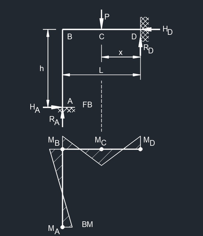
Diagram Symbols
Bending moment diagram (BMD) - Used to determine the bending moment at a given point of a structural element. The diagram can help determine the type, size, and material of a member in a structure so that a given set of loads can be supported without structural failure.
Free body diagram (FBD) - Used to visualize the applied forces, moments, and resulting reactions on a structure in a given condition.
Shear force diagram (SFD) - Used to determine the shear force at a given point of a structural element. The diagram can help determine the type, size, and material of a member in a structure so that a given set of loads can be supported without structural failure.
Uniformly distributed load (UDL) - A load that is distributed evenly across the entire length of the support area.
![]()