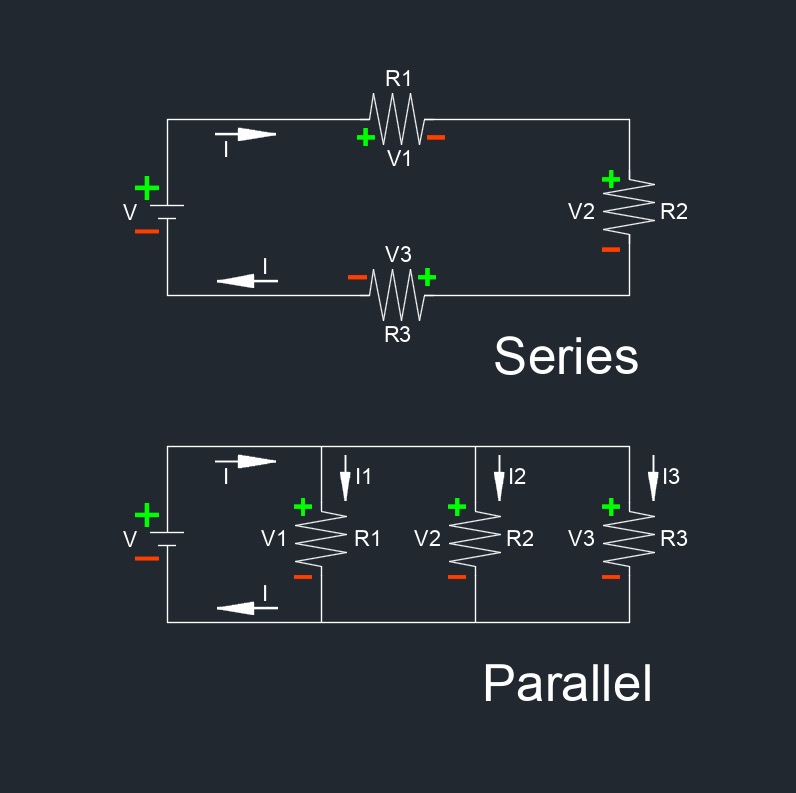
Parallel and Series Circuit
Parallel and series are two different configurations in which electrical components can be connected within a circuit.
Parallel Circuit formulas |
||
|
\( \dfrac{ 1}{R_t } \;=\; \dfrac{1}{R_1} + \dfrac{1}{R_2} + \dfrac{1}{R_3} \; + ... +\; \dfrac{1}{R_n} \) (Resistor) \(C_t \;=\; C_1 + C_2 + C_3 \; + ... + \; C_n \) (Capacitor) \( \dfrac{ 1}{L_t } \;=\; \dfrac{1}{L_1} + \dfrac{1}{L_2} + \dfrac{1}{L_3} \; + ... +\; \dfrac{1}{L_n} \) (Inductor) |
||
| Symbol | English | Metric |
| \(R\) = Resistance | \(\Omega\) | \(\Omega\) |
| \(C\) = Capacitor | \(F\) | \(F\) |
| \(L\) = Inductor | \(H\) | \(H\) |
 Parallel Configuration - In a parallel configuration, electrical components are connected in such a way that they share the same voltage across their terminals. Each component has its own path for the current to flow. In a parallel circuit, if one component fails, it does not necessarily affect the operation of the other components. Examples of parallel connections include household electrical outlets and the wiring in many appliances.
- Characteristics of a parallel circuit:
- Each component has the same voltage across it.
- The total current flowing into the junction splits into separate branches.
- The total resistance decreases as more branches are added.
Series Circuit formulas |
||
|
\(R_t \;=\; R_1 + R_2 + R_3 \; + ... + \; R_n \) (Resistor) \( \dfrac{1}{C_t} \;=\; \dfrac{1}{C_1} + \dfrac{1}{C_2} + \dfrac{1}{C_3} \; + ... +\; \dfrac{1}{C_n} \) (Capacitor) \(L_t \;=\; L_1 + L_2 + L_3 \; + ... + \; L_n \) (Inductor) |
||
| Symbol | English | Metric |
| \(R\) = Resistance | \(\Omega\) | \(\Omega\) |
| \(C\) = Capacitor | \(F\) | \(F\) |
| \(L\) = Inductor | \(H\) | \(H\) |
 Series Configuration - In a series configuration, electrical components are connected sequentially, so the same current flows through each component. The total resistance of the circuit is the sum of the individual resistances. If one component fails in a series circuit, the entire circuit may fail or be affected, as the current cannot bypass the failed component. Examples of series connections include Christmas tree lights and flashlight circuits.
- Characteristics of a series circuit:
- The same current flows through each component.
- The total resistance of the circuit is the sum of the individual resistances.
- The total voltage across the circuit is the sum of the voltages across each component.
The choice between series and parallel configurations depends on various factors such as the specific requirements of the circuit, desired functionality, cost considerations, and reliability concerns. Each configuration has its own set of advantages and disadvantages that should be carefully considered during the design process.
Parallel Circuit Advantages and Disadvantages | |
|---|---|
| Advantages | Disadvantages |
|
|

Series Circuit Advantages and Disadvantages | |
|---|---|
| Advantages | Disadvantages |
|
|
