Gear
Pump, Engine, Horsepower, Gear, Glossary, Rotating Equipment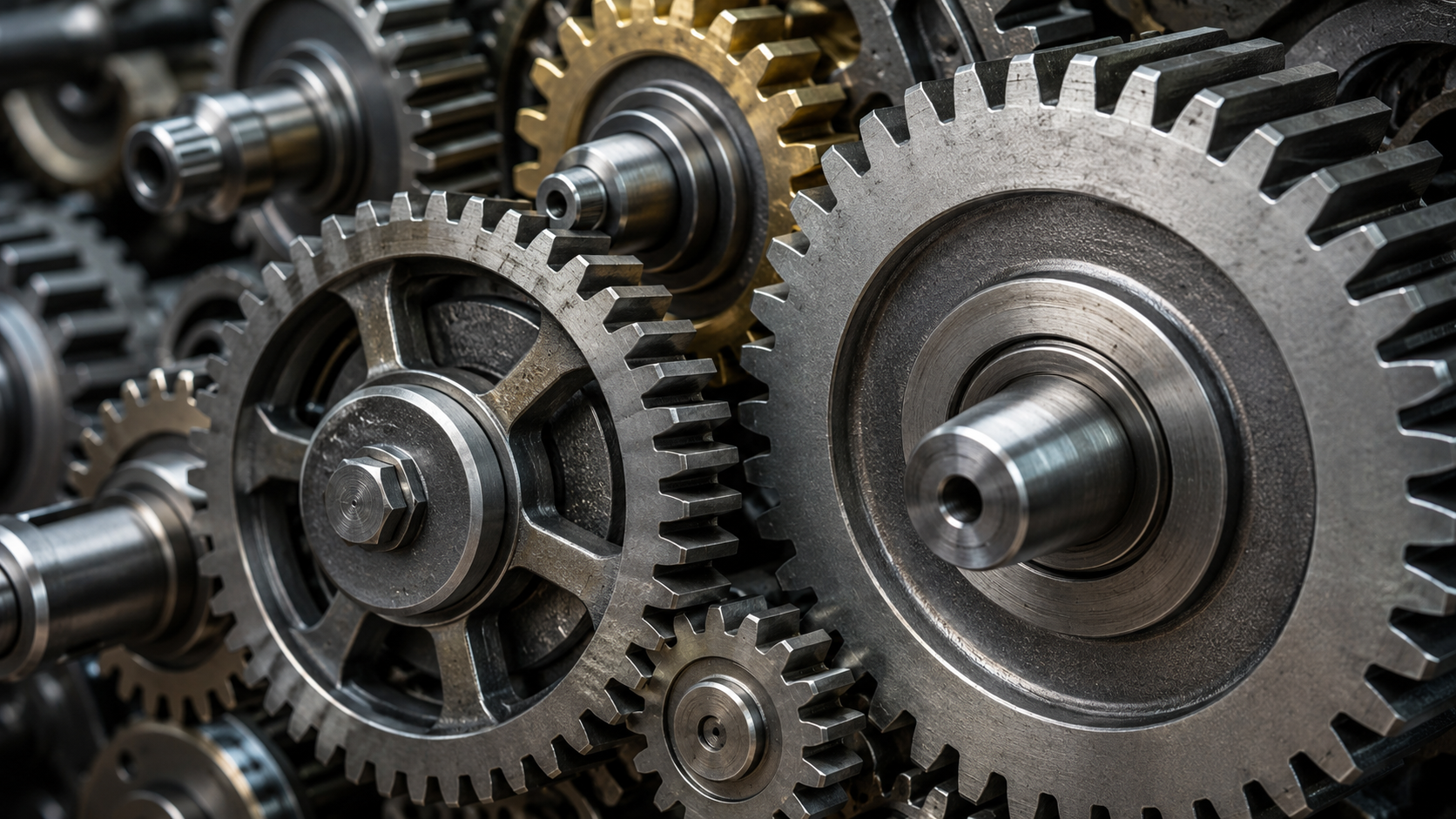 Gear is a machine element consisting of a rotating wheel or cylinder with precisely formed teeth that mesh with the teeth of another gear or a compatible toothed component, such as a rack. Its primary purpose is to transmit mechanical power and rotational motion from one shaft to another. When the teeth of one gear engage the teeth of another, force is transferred through the contact of the teeth, allowing torque and rotational speed to be transmitted in a controlled and predictable manner. Gears are fundamental components used in machinery because they provide a positive mechanical drive with virtually no slip under normal operating conditions.
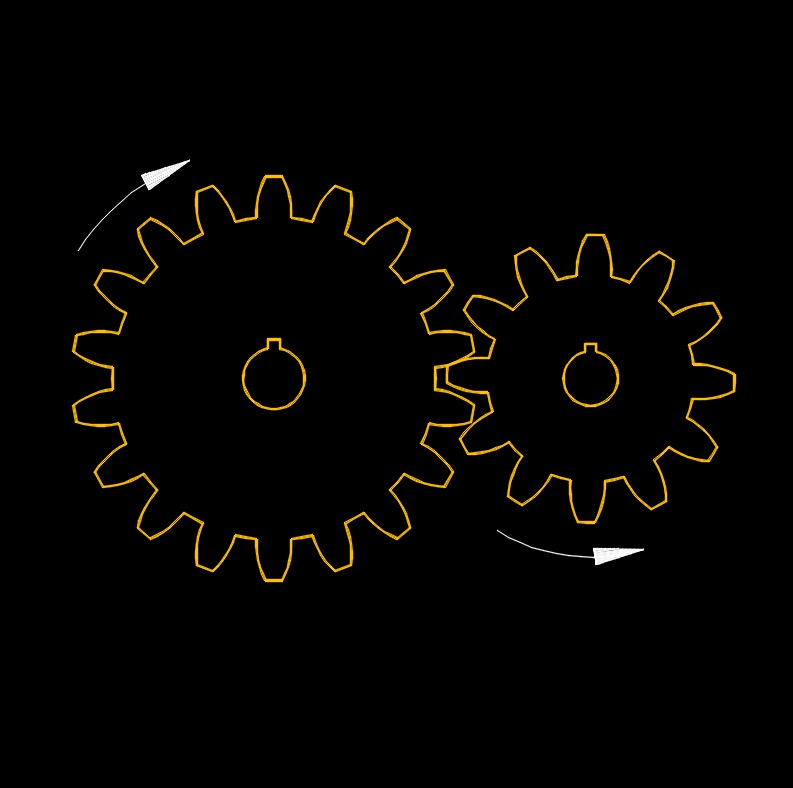
The most important function of a gear system is to modify the relationship between rotational speed and torque. When a small gear drives a larger gear, the output shaft rotates more slowly but with greater torque. Conversely, when a larger gear drives a smaller gear, the output shaft rotates faster but with reduced torque. This ability to trade speed for torque, or torque for speed, makes gears essential in machines ranging from clocks, automobiles, turbines, pumps, and heavy machinery. The ratio of the number of teeth on mating gears determines the speed ratio and torque ratio between the input and output shafts.
| Science |
| Applied Science |
| Engineering |
| Mechanical Engineering |
| Manufacturing |
Gears also provide a means of changing the direction of rotation and the orientation of power transmission. For example, parallel shafts are commonly connected by spur or helical gears, intersecting shafts by bevel gears, and nonparallel, nonintersecting shafts by worm gears or other specialized gear arrangements. Through these configurations, gears allow mechanical power to be transmitted efficiently between shafts located in different positions within a machine.
Gear Shaft Axis Position Design Classification
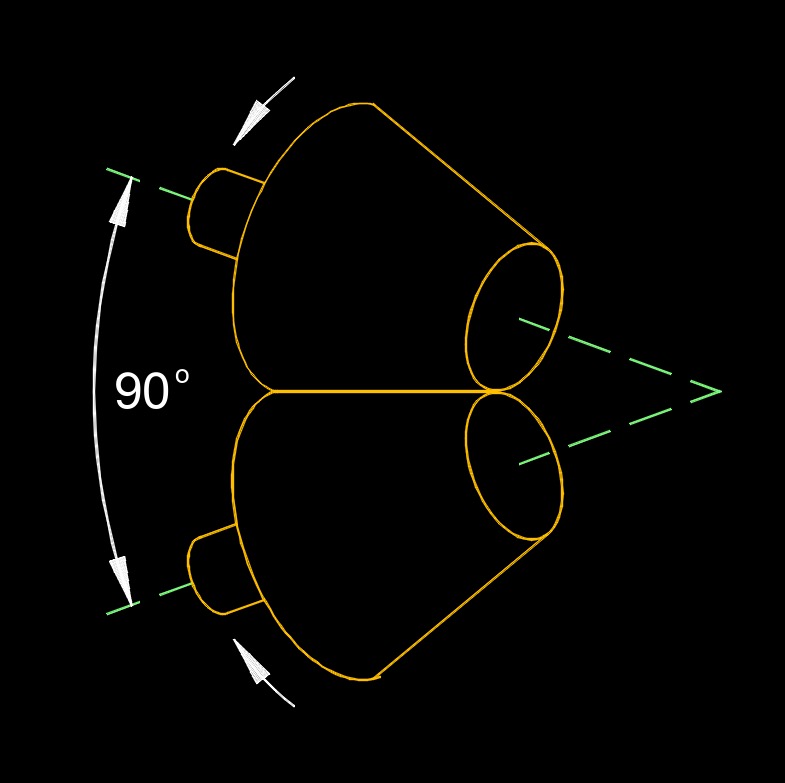 Intersecting Shaft - They are designed to transmit power and motion between 90 degree angular intersecting shafts having beveled gears.
- Bevel Gear - Used to transmit power between shafts that intersect at a 90 degree angle. They are used in applications where a right angle gear drive is required.
- Hypoid Bevel Gear - Like a spiral bevel gears, but with hyperbolic pitch surfaces instead of conical ones.
- Face Gear - Looks like a bevel gear that is limited to 90° intersecting axes. This is a circular disc with a ring of teeth cut in its side face.
- Spiral Bevel Gear - They have a curved angle of teeth placement. It is more angled and also provides gradual teeth to teeth contact than that of straight bevel gears.
- Straight Bevel Gear - They have a conical pitch surface, but the teeth are straight, consistently tapering toward the apex of the system.
- Zero Bevel Gear - The combination of both spiral and straight gears having curved teeth that are placed straight on the conical surface.
- Hypoid Bevel Gear - Like a spiral bevel gears, but with hyperbolic pitch surfaces instead of conical ones.
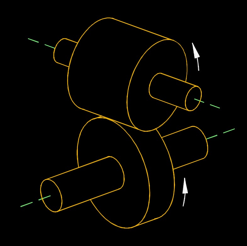
 Parallel Shaft - They are designed to transmit power and motion between parallel shafts. The angle between driving and driven shaft is 0 degree.
- Helical Gear - These are cylindrical gears whose teeth are not parallel to the axis of rotation. The teeth are angled and appear as a segment of a helix. Helical gears can transmit power between parallel or right angle axes.
- Single Helical Gear - Single helical gears have a single row of angled teeth cut or embedded around the perimeter of the gear body.
- Double Helical Gear - These gears have a groove in the middle, between the teeth, whereas herringbone gears do not. This arrangement cancels out the axial forces on each set of teeth, so larger helix angles can be used.
- Harringbone Gear - A type of double helical gear in which the two teeth track touches each other rather than being separated by a channel. This forms a V shaped structure.
- Sprocket Gear - A sprocket has a shaft as part of the gear that usually interacts directly with some part of the machinery, whereas gears can and often do push against each other first, then use that collective movement to influence some larger mechanical process.
- Bushed Sprocket
- Chain Sprocket
- Double Plus Sprocket
- Drive Sprocket
- Drum Sprocket
- Duplex Sprocket
- Idler Sprocket
- Industrial Sprocket
- Multi-standard Sprocket
- Quick Disconect Sprocket
- Shaft Sprocket
- Simplex Sprocket
- Steel Split Sprocket
- Taper-lock Sprocket
- Triplex Sprocket
- Spur Gear - A cylindrical shaped gear in which the teeth are parallel to the axis. This causes the gears to produce radial reaction loads on the shaft, but not axial loads.
 Non-intersecting and Non-parallel Shaft - They are designed to transmit power and motion between 90 degree angle non-intersecting, non-coplanar shafts.
- Screw Gear - A pair of cylindrical gears used to drive shafts where the teeth of one or both members of the pair are of screw form.
- Worm Gear - This gear transmits power through right angles on non-intersecting shafts. Worm gears produce thrust load and are good for high shock load applications but offer very low efficiency in comparison to the other gears.
- Non-throated Worm Gear - A helical gear with a straight worm. Tooth contact is a single moving point on the worm drive. both the worm and the driven gear is not throated
- Straight Throated Worm Gear - Only the contour of the gear teeth is modified to get the increased amount of contact surface.
- Double Throated Worm Gear - The teeth profile of the gear as well as the shape of the worm threads are modified to achieve better engagement. The modification is in line with the circular shape of the gear teeth. The engagement is achieved throughout the length and width of the worm gear.
Gear Teeth
Straight Gear Teeth - The teeth axis is parallel to the shaft axis.
Inclined Gear Teeth - The teeth axis is at some angle.
Curve Gear Teeth - The teeth are curved on the gear rim surface.
 Gear Design Classification
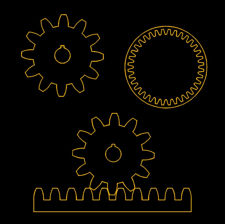
External Gear - Those type of gears which have their cogs formed on the outside surface of a cylinder or cone.
Internal Gear - A cylindrical shaped gear, but with the teeth are inside the circular ring. It can mesh with a spur gear.
Rack and Pinion Gear - A rack is a circular gear, and a pinion is a linear gear. Together, they turn rotational motion into linear motion
- Gear Rack - A linear shaped gear which can mesh with a spur gear with any number of teeth.
- Pinion Gear - Is cylindrical in shape.
 Gear Velocity
Low Gear Velocity - Having a velocity less than 3 \(\frac{m}{s}\).
Medium Gear Velocity - Having a velocity between 3 \(\frac{m}{s}\) and 15 \(\frac{m}{s}\).
High Gear Velocity - Having a velocity more than 15 \(\frac{m}{s}\).
![]()