Orifice Pressure Loss (horizontal orifice and nozzle) formula |
||
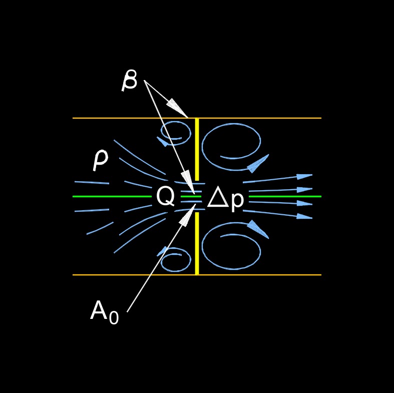
| \( \Delta p \;=\; \left( \dfrac{1}{2} \cdot \rho \right) \cdot ( 1 - \beta^4 ) \cdot \left( \dfrac{ Q }{ C_d \cdot A_o \cdot Y } \right)^2 \) (Horizontal Orifice and Nozzle) | ||
| Symbol | English | Metric |
| \( \Delta p \) = Pressure lLoss | \(lbf \;/\; in^2\) | \(Pa\) |
| \( \rho \) (Greek symbol rho) = Density | \(lbm \;/\; ft^3\) | \(kg \;/\; m^3\) |
| \( \beta \) (Greek symbol beta) = Ratio of Pipe Inside Diameter to Orifice Diameter | \( dimensionless \) |
\( dimensionless \) |
| \( Q \) = Orifice Flow Rate | \(ft^3 \;/\; sec\) | \(m^3 \;/\; s\) |
| \( C_d \) = Orifice Discharge Coefficient | \( dimensionless \) | \( dimensionless \) |
| \( A_o \) = Orifice Area | \( in^2 \) | \( mm^2 \) |
| \( Y \) = Expansion Coefficient (Y = 1 for Incompressible Flow) | \( dimensionless \) | \( dimensionless \) |
Solve for: |
||
|
\( Y = C_{d,c} \;/\; C_{d,i} \) \( C_{d,c} \) = discharge coefficient compressible fluid \( C_{d,i} \) = discharge coefficient incompressible fluid \( \beta \) (Greek symbol beta) = \(d_0 \;/\; d_u\) \( d_o \) = orifice or nozzle diameter \( d_u \) = upstream pipe inside diameter from orifice or nozzle |
||
 Orifice pressure loss, also called orifice pressure drop or orifice flow, refers to the decrease in pressure that occurs when a fluid (liquid or gas) passes through a constriction or an orifice in a pipeline, pipe, or other flow system. This phenomenon is commonly encountered in various engineering applications, including fluid mechanics, chemical engineering, and process control.
The orifice itself is a specifically designed opening or hole in a pipe or plate, typically circular in shape, that is used to control and measure the flow of fluid. When a fluid flows through the orifice, it experiences a change in velocity and pressure. This change in pressure is due to the restriction of the flow area, and it can be used for various purposes, such as regulating flow rates, measuring flow rates, or mixing fluids.
Key Points about Crifice Pressure Loss
Orifice Size - The diameter of the orifice significantly influences the pressure drop. Smaller orifices result in greater pressure losses, as they create more restriction to the flow.
Fluid Properties - The physical properties of the fluid, such as density and viscosity, affect the pressure loss. Different fluids will exhibit different pressure drop characteristics for the same orifice size.
Flow Rate - The rate at which the fluid flows through the orifice is a critical factor. Higher flow rates generally result in larger pressure drops.
Orifice Shape - While circular orifices are common, other shapes like square, rectangular, or even more complex geometries can affect pressure loss differently.
Approach Velocity - The velocity of the fluid entering the orifice can impact pressure loss. It's often ideal to have a uniform approach velocity.
Reynolds Number - The Reynolds number, which depends on fluid velocity, density, viscosity, and orifice size, determines whether the flow is laminar or turbulent and affects pressure loss accordingly.
Orifice Plate Design - Orifice plates can be designed with specific configurations, such as concentric, eccentric, or segmental, to achieve different flow control objectives.
Orifice Pressure Loss vertical orifice and nozzle formula |
||
| \( \Delta p \;=\; (1/2 \; \rho) \; ( 1 - \beta^4 ) \; ( Q \;/\; C_d \; A_o \; Y )^2 \; - \rho \; g \; \Delta y \) (Vertical Orifice and Nozzle) | ||
| Symbol | English | Metric |
| \( \Delta p \) = Pressure Loss | \(lbf \;/\; in^2\) | \(Pa\) |
| \( \rho \) (Greek symbol rho) = Density | \(lbm \;/\; ft^3\) | \(kg \;/\; m^3\) |
| \( \beta \) (Greek symbol beta) = Ratio of Pipe Inside Diameter to Orifice Diameter | \( dimensionless \) | \( dimensionless \) |
| \( Q \) = Orifice Flow Rate | \(ft^3 \;/\; sec\) | \(m^3 \;/\; s\) |
| \( C_d \) = Orifice Discharge Coefficient | \( dimensionless \) | \( dimensionless \) |
| \( A_o \) = Orifice Area | \( in^2 \) | \( mm^2 \) |
| \( Y \) = Expansion Coefficient (Y = 1 for Incompressible Flow) | \( dimensionless \) | \( dimensionless \) |
| \( g \) = Gravitational Acceleration | \(ft \;/\; sec^2\) | \(m \;/\; s^2\) |
| \( \Delta y \) = Eevation Change ( \(\Delta y = y_1 - y_2\) ) | \( ft \) | \( m \) |
Solve for: |
||
|
\( Y = C_{d,c} \;/\; C_{d,i} \) \( C_{d,c} \) = discharge coefficient compressible fluid \( C_{d,i} \) = discharge coefficient incompressible fluid \( \beta \) (Greek symbol beta) = \(d_0 \;/\; d_u\) \( d_o \) = orifice or nozzle diameter \( d_u \) = upstream pipe inside diameter from orifice or nozzle |
||
Engineers use equations and charts, such as the Bernoulli equation and various empirical equations, to calculate orifice pressure loss in practical applications. This information is valuable for designing and optimizing flow systems, ensuring proper fluid control, and maintaining the safety and efficiency of industrial processes.
![]()