Butterfly valve, abbreviated as \(BTFLV\), is a quarter turn valve (90° or less) with a circular disk as its closing element. The standard design has the valve stem running through the disk, giving a symmetrical appearance. Other designs offset the stem. Advantages include less wear and tear on the disk and seats, and tighter shut-off capabilities. When space is limited, sometimes larger valves may use a hand wheel with a gear arrangement. Butterfly valves are rather easy to maintain. These valves are used for gases, liquids, slurries, powders, and vacuum.
Butterfly Valve DatasheetsFace to face dimensions for full and standard port valves is the same. All ball valves 2" and below are both standard and full port valves. | |||
|---|---|---|---|
| Butterfly Type | Datasheets | Butterfly Type | Datasheets |
   |
|
 |
|
There are Two Butterfly Valve Categories
Category A - Manufacturer's rated cold working pressure (CWP) butterfly valves, usually with a concentric disc and seat configuration. Sizes covered are NPS 2 to NPS 48 for valves having ASME Class 125 or Class 150 flange bolting patterns.
Category B - Pressure-temperature rated butterfly valves that have an offset seat and either an eccentric or a concentric disc configuration. These valves may have a seat rating less than the body rating. Sizes covered are NPS 3 to NPS 24 for Classes 150, 300, and 600.
Butterfly Valve Design Classification
Double Offset Butterfly Valve - This valve features the stem center deviated from the center of the disc and valve. With this structure, the valve disc can leave the valve seat quickly, greatly reducing unnecessary over compression and scraping between them. This structure also helps decrease the wearing process and prolongs the operational life of the valve.
Fire Tight Valve - When using valves in a service that may provide fuel to a fire, it is important to ensure that they are fire tight. Typically the seat in a soft seated fire tight valve contains a metal strip that will provide additional sealing should the seat be burnt or melted away. Fire tight valves can be found on fuel gas applications, VRU systems and in other flammable systems.
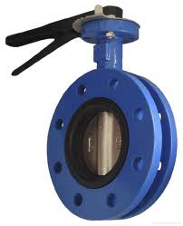
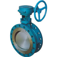
Flange Style Butterfly Valve - A butterfly valve with a flange on each end. These have a larger face to face dimension than the wafer and lug style butterfly valves and should not be used when there is limited space. These valves connect directly to the flanges by means of machine bolt to each side of the valve. If the valve torque is high or valve operations become too frequen, a manual flanged butterfly valves can be automated if need be.
High Performance Butterfly Valve - A valve in which the stem is not collinear to the disc centerline but rather offset from the center. The use of offset design helps to enhance uniform tight shut-off against the valve seat and also reduce wear due to friction. This valve can be used for shut-off and throttling fluid flow applications. This valve is made to handle different fluids from general fluid flow applications to viscous and corrosive fluids. The corrosive fluids can be gases or steam. High-performance butterfly valves are mostly of large sizes like 60 inch diameter.
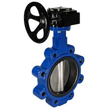
Lug Style Butterfly Valve - Lug butterfly valves connect directly to the flanges by means of a lug or machine bolt. Since these are attached directly to the flanges, each length of pipe on either side of hte valve can be removed and replaced independant of the other. Unlike a wafer type butterfly valve, a lug style valve can serve as an end of the line valve. Lug style butterfly valves have the same face to face dimensions as a wafer style butterfly valve. The valves can be used for end of line service but a blind flange is always recommended. The valves are manufactured to be compatible with either pneumatic or electric actuation.
Triple Offset Butterfly Valve - The design eliminates the rubbing between the seat and seal ring through the flow path, reducing seat and seal wear and extending cycle life. They are used in applications similar to gate valves, where a metal seat is required, and tight shutoff and/or quarter-turn actuation is desired. Triple offset butterfly valves can open and close more quickly and can be frequently operated, even if there is an emergency shutoff. This valve has low torque and is recommended for both high and low temperature applications.
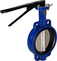
Wafer Style Butterfly Valve - Most wafer style butterfly valves are engineered with four holes that align with the connected pipeline. The valve is sandwiched between two flanges. The rubber valve seat creates a strong seal between the valve and flange connection. Unlike lug style butterfly valves, wafer style butterfly valves cannot be used as pipe ends or end of line service. The entire line must be shut down if either side of the valve requires maintenance. Wafer style butterfly valves are manufactured to be compatible with either pneumatic or electric actuation. Disc and seat material should be determined based on application and flow media.
Zero Offset Butterfly Valve - Concentric or rubber seated are other names for the zero-offset design. Zero offset means there is no offset by the stem of the valve. The valve seals via interference along the disc edge at the stem between the disc and the rubber seat.
Resultant is a single vector that represents the combined effect of two or more individual vectors acting on a body or at a point. It shows the overall magnitude and direction of all the forces, velocities, or other vector quantities applied. In other words, the resultant is the vector sum of all the component vectors and can replace them without changing the physical effect on the system. For example, if several forces act on an object, the resultant force determines the object’s motion according to Newton’s laws. The process of finding the resultant involves combining the vectors using graphical or mathematical methods such as the parallelogram law, triangle law, or vector addition formulas. Modulus is a measuring quantity or parameter that expresses the magnitude or strength of a property rather than a direction. In science and engineering, it is used to indicate how strongly something responds to an influence, such as how resistant a material is to deformation or how large a mathematical quantity is in absolute terms. Depending on the context, modulus can refer to the stiffness of a material (as in elastic modulus), the absolute value of a number (as in mathematical modulus), or a constant that scales a physical response, but in all cases it conveys the idea of a standardized measure of intensity or magnitude. ASME Standards Length (L) of a square bolt is measured from underside of head to the end of the bolt. Bolt Size Body Diameter D Width Across Flat A Width Across Corner B Thickness C Max Min Basic Max Min Max Min Basic Max Min 1/4 0.260 0.237 7/16 0.375 0.362 0.530 0.498 7/32 0.188 0.156 5/16 0.324 0.298 1/2 0.500 0.484 0.707 0.665 17/64 0.220 0.186 3/8 0.388 0.360 5/8 0.562 0.544 0.795 0.747 21/64 0.268 0.232 7/16 0.452 0.421 3/4 0.625 0.603 0.884 0.828 9/32 0.316 0.278 1/2 0.515 0.482 13/16 0.750 0.725 1.061 0.995 7/16 0.348 0.308 5/8 0.642 0.605 1 0.938 0.906 1.326 1.244 35/64 0.444 0.400 3/4 0.768 0.729 1 1/8 1.125 1.088 1.591 1.494 21/32 0.524 0.476 7/8 0.895 0.852 1 5/16 1.312 1.269 1.856 1.742 49/64 0.620 0.568 1 1.022 0.976 1 1/2 1.500 1.450 2.121 1.991 7/8 0.684 0.628 1 1/8 1.149 1.098 1 11/16 1.688 1.631 2.386 2.239 1 0.780 0.720 1 1/4 1.277 1.223 1 7/8 1.875 1.812 2.652 2.489 1 3/32 0.876 0.812 1 3/8 1.404 1.345 2 1/16 2.062 1.994 2.917 2.738 1 13/64 0.940 0.872 1 1/2 1.531 1.470 2 1/4 2.250 2.175 3.182 2.986 1 5/16 1.036 0.964 Size A B C Size B
Resultant
Modulus
Bolt - Square, ANSI (in)


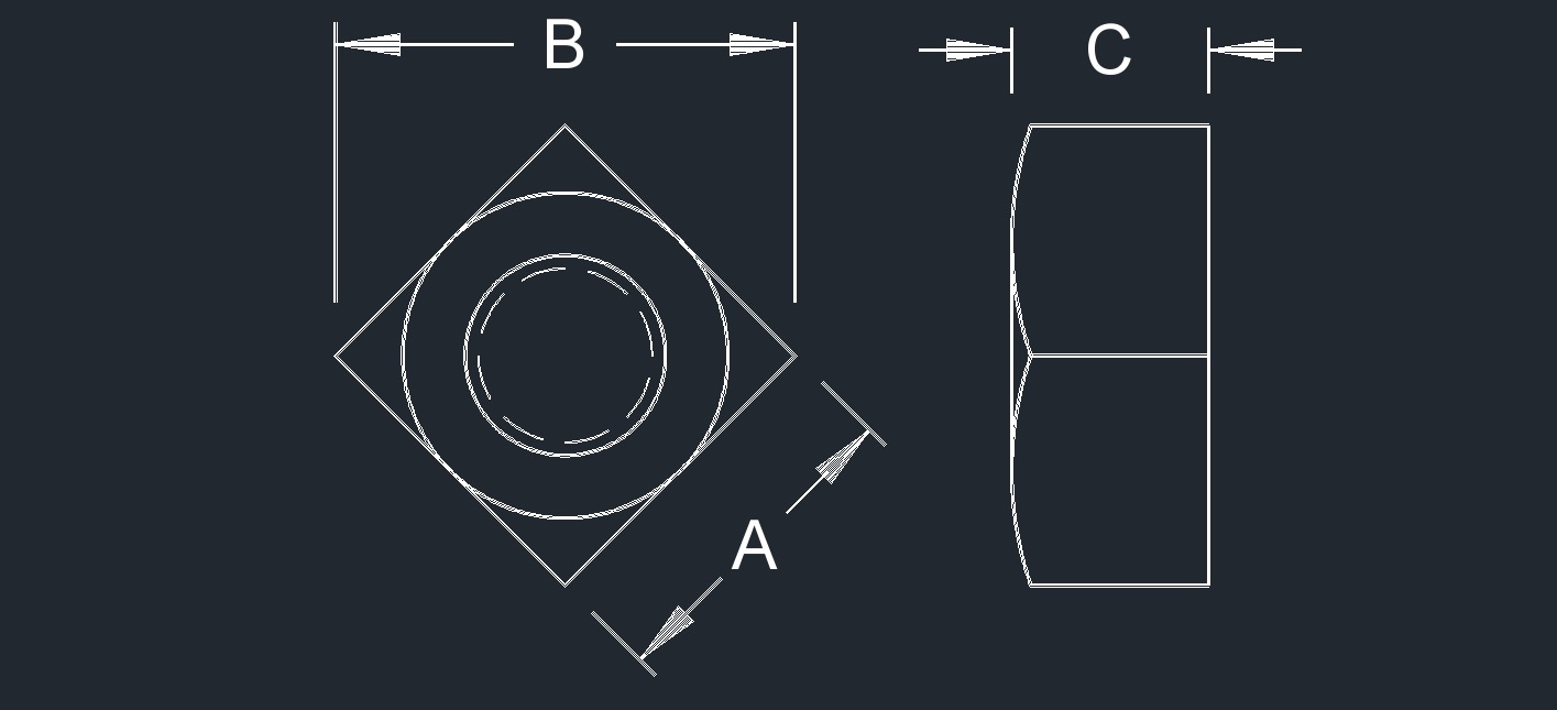
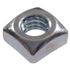
Square Nut (in)
Standard
Square Nut (in) Datasheet
Bolt
Width Across Flat
Width Across Corner
Thickness
Basic Max Min Max Min Basic Max Min
1/4
7/16
0.438
0.428
0.619
0.554
7/32
0.235
0.203
5/16
1/2
0.500
0.489
0.795
0.721
17/64
0.283
0.249
3/8
5/8
0.625
0.606
0.884
0.802
21/64
0.346
0.310
1/2
13/16
0.812
0.788
1.149
1.052
7/16
0.458
0.418
5/8
1
1.000
0.969
1.414
1.300
35/64
0.569
0.525
3/4
1 1/8
1.125
1.088
1.591
1.464
21/32
0.680
0.632
7/8
1 5/16
1.312
1.269
1.856
1.712
49/64
0.792
0.740
1
1 1/2
1.500
1.450
2.121
1.961
7/8
0.903
0.847
1 1/8
1 11/16
1.688
1.631
2.386
2.209
1
1.030
0.970
1 1/4
1 7/8
1.875
1.812
2.652
2.458
1 3/32
1.126
1.062
1 3/8
2 1/16
2.062
1.994
2.917
2.708
1 13/64
1.237
1.169
1 1/2
2 1/4
2.250
2.175
3.182
2.956
1 5/16
1.348
1.276
Slotted Flat Cap Screw (in)
Standard
Slotted Flat Cap Screw (in) Datasheet
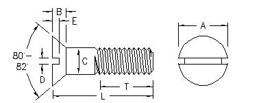
Screw
Body Diameter
CHead Diameter
AHead Height
Slot Width
DSlot Depth
EMax Min Max Edge Sharp Min Edge Rounded or Flat Ref Max Min Max Min
1/2
0.5000
0.4930
0.875
0.791
0.210
0.106
0.091
0.103
0.068
5/8
0.6250
0.6170
1.125
1.020
0.281
0.133
0.116
0.137
0.091
3/4
0.7500
0.7420
1.375
1.251
0.352
0.149
0.131
0.171
0.115
Butterfly Valve Advantages and Disadvantages | |
|---|---|
| Advantages | Disadvantages |
|
|