Article Links |
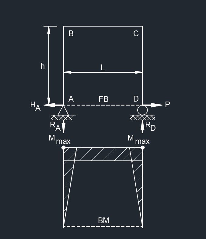
Three Member Frame - Pin/Roller Side and Bottom Point Load formulas
| \(\large{ R_A = R_D = 0 }\) | |
| \(\large{ H_A = P }\) | |
| \(\large{ M_{max} \;(at \; B \;and\; C) = P\;h }\) | |
| \(\large{ \Delta_{Dx} = \frac{P\;h^2}{3 \; \lambda \; I} \; \left(3\;L+2\;h\right) }\) |
Where:
| Units | English | Metric |
| \(\large{ \Delta }\) = deflection or deformation | \(\large{in}\) | \(\large{mm}\) |
| \(\large{ h }\) = height of frame | \(\large{in}\) | \(\large{mm}\) |
| \(\large{ H }\) = horizontal reaction load at bearing point | \(\large{lbf}\) | \(\large{N}\) |
| \(\large{ I_h }\) = horizontal member second moment of area (moment of inertia) | \(\large{in^4}\) | \(\large{mm^4}\) |
| \(\large{ I_v }\) = vertical member second moment of area (moment of inertia) | \(\large{in^4}\) | \(\large{mm^4}\) |
| \(\large{ M }\) = maximum bending moment | \(\large{lbf-in}\) | \(\large{N-mm}\) |
| \(\large{ \lambda }\) (Greek symbol lambda) = modulus of elasticity | \(\large{\frac{lbf}{in^2}}\) | \(\large{PA}\) |
| \(\large{ A, B, C, D }\) = point of intrest on frame | - | - |
| \(\large{ L }\) = span length under consideration | \(\large{in}\) | \(\large{mm}\) |
| \(\large{ P }\) = total concentrated load | \(\large{lbf}\) | \(\large{N}\) |
| \(\large{ R }\) = vertical reaction load at bearing point | \(\large{lbf}\) | \(\large{N}\) |
diagrams
- Bending moment diagram (BMD) - Used to determine the bending moment at a given point of a structural element. The diagram can help determine the type, size, and material of a member in a structure so that a given set of loads can be supported without structural failure.
- Free body diagram (FBD) - Used to visualize the applied forces, moments, and resulting reactions on a structure in a given condition.
- Shear force diagram (SFD) - Used to determine the shear force at a given point of a structural element. The diagram can help determine the type, size, and material of a member in a structure so that a given set of loads can be supported without structural failure.
- Uniformly distributed load (UDL) - A load that is distributed evenly across the entire length of the support area.
![]()